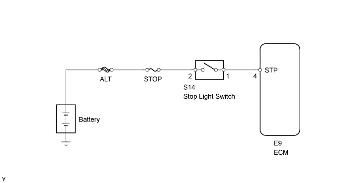
AUTOMATIC TRANSMISSION SYSTEM > Stop Light Switch Circuit |
| DATA LIST |
Warm up the engine.
Turn the ignition switch off.
Connect the intelligent tester to the DLC3.
Turn the ignition switch to ON.
Turn the intelligent tester on.
Enter the following menus: Powertrain / Engine and ECT / Data List.
According to the display on the intelligent tester, read the Data List.
| Tester Display | Measurement Item/Range | Normal Condition | Diagnostic Note |
| Stop Light Switch | Stop light switch status/ ON or OFF |
| - |
| 1.INSPECT STOP LIGHT SWITCH ASSEMBLY |
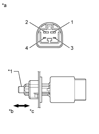 |
Remove the stop light switch assembly.
Measure the resistance according to the value(s) in the table below.
| Tester Connection | Switch Condition | Specified Condition |
| 1 - 2 | Pin not pushed | Below 1 Ω |
| 3 - 4 | Pin pushed | Below 1 Ω |
| 1 - 2 | Pin pushed | 10 kΩ or higher |
| 3 - 4 | Pin not pushed | 10 kΩ or higher |
| *1 | Pin |
| *a | Component without harness connected (Stop Light Switch Assembly) |
| *b | Not pushed |
| *c | Pushed |
|
| ||||
| OK | |
 |
| 2.CHECK HARNESS AND CONNECTOR (BATTERY - ECM) |
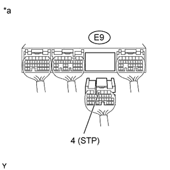 |
Disconnect the E9 ECM connector.
Measure the voltage according to the value(s) in the table below.
| Tester Connection | Condition | Specified Condition |
| E9-4 (STP) - Body ground | Brake pedal depressed | 11 to 14 V |
| E9-4 (STP) - Body ground | Brake pedal released | Below 1 V |
| *a | Rear view of wire harness connector (to ECM) |
|
| ||||
| OK | ||
 | ||
| ||
