 |
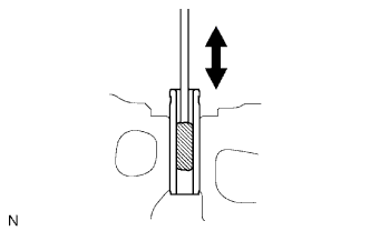
Using a valve guide bushing brush and solvent, clean all the guide bushes.
CYLINDER HEAD > INSPECTION |
| 1. CLEAN CYLINDER HEAD SUB-ASSEMBLY |
Using a gasket scraper, remove all the gasket material from the surface of the cylinder head that contacts the cylinder block.
Using a soft brush and solvent, thoroughly clean the cylinder head.
|
Using a valve guide bushing brush and solvent, clean all the guide bushes.
| 2. INSPECT CYLINDER HEAD SUB-ASSEMBLY |
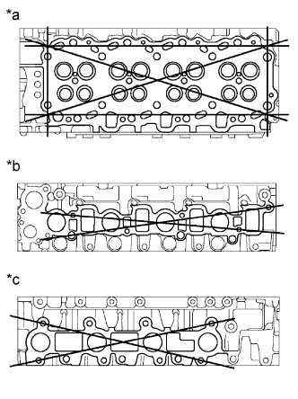 |
Inspect the cylinder head for warpage.
Using a precision straightedge and feeler gauge, measure the surfaces of the cylinder head that contact the cylinder block and manifolds for warpage.
| *a | Cylinder Block Side |
| *b | Intake Manifold Side |
| *c | Exhaust Manifold Side |
Inspect the cylinder head for cracks.
Using a dye penetrant, check the combustion chamber, intake ports, exhaust ports and cylinder block surface for cracks.
If there are cracks, replace the cylinder head sub-assembly.
| 3. CLEAN INTAKE VALVE |
Using a gasket scraper, chip off any carbon from the valve head.
Using a wire brush, thoroughly clean the intake valve.
| 4. INSPECT INTAKE VALVE |
Using a micrometer, measure the diameter of the valve stem.
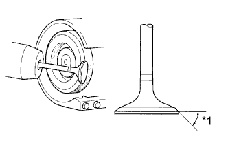 |
Check the valve face angle.
Grind the valve enough to remove any pits and carbon.
Check that the valve is ground to the correct valve face angle.
| *1 | Valve Face Angle |
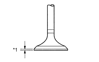 |
Check the valve head margin thickness.
| *1 | Margin Thickness |
Check the overall valve length.
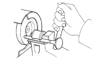 |
Check the surface of the valve stem tip for wear.
If the valve stem tip is worn, resurface the tip with a grinder or replace the intake valve.
| 5. CLEAN EXHAUST VALVE |
Using a gasket scraper, chip off any carbon from the valve head.
Using a wire brush, thoroughly clean the exhaust valve.
| 6. INSPECT EXHAUST VALVE |
Using a micrometer, measure the diameter of the valve stem.
|
Check the valve face angle.
Grind the valve enough to remove any pits and carbon.
Check that the valve is ground to the correct valve face angle.
| *1 | Valve Face Angle |
|
Check the valve head margin thickness.
| *1 | Margin Thickness |
Check the overall valve length.
|
Check the surface of the valve stem tip for wear.
If the valve stem tip is worn, resurface the tip with a grinder or replace the exhaust valve.
| 7. INSPECT INNER COMPRESSION SPRING |
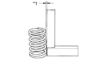 |
Using a steel square, measure the deviation of the spring.
| *1 | Deviation |
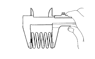 |
Using a vernier caliper, measure the free length of the spring.
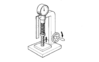 |
Using a spring tester, measure the tension of the valve spring at the specified installed length.
| 8. INSPECT INTAKE VALVE GUIDE BUSH |
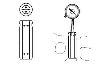 |
Using a caliper gauge, measure the inside diameter of the valve guide bush.
Subtract the valve stem diameter measurement (refer to the intake valve inspection procedures above) from the valve guide bush inside diameter measurement.
| 9. INSPECT EXHAUST VALVE GUIDE BUSH |
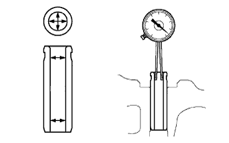 |
Using a caliper gauge, measure the inside diameter of the valve guide bush.
Subtract the valve stem diameter measurement (refer to the exhaust valve inspection procedures above) from the valve guide bush inside diameter measurement.
| 10. INSPECT INTAKE VALVE SEAT |
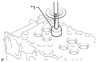 |
Using a 45° carbide cutter, resurface the valve seats. Remove only enough metal to clean the valve seats.
| *1 | 45° Carbide Cutter |
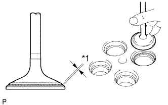 |
Apply a light coat of Prussian blue to the valve face.
Lightly press the valve face against the valve seat.
Check the valve face and valve seat.
Check that the contact surfaces of the valve seat and valve face are in the middle area of their respective surfaces, with the width between 1.2 and 1.6 mm (0.0472 and 0.0630 in.).
| *1 | Width |
Check that the contact surfaces of the valve seat and valve face are even around the entire valve seat.
If the contact surfaces are not as specified, resurface the intake valve seat. If necessary, replace the intake valve.
| 11. INSPECT EXHAUST VALVE SEAT |
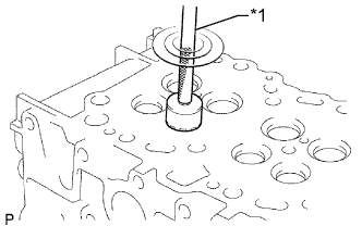 |
Using a 45° carbide cutter, resurface the valve seats. Remove only enough metal to clean the valve seats.
| *1 | 45° Carbide Cutter |
|
Apply a light coat of Prussian blue to the valve face.
Lightly press the valve face against the valve seat.
Check the valve face and valve seat.
Check that the contact surfaces of the valve seat and valve face are in the middle area of their respective surfaces, with the width between 1.6 and 2.0 mm (0.0630 and 0.0787 in.)
| *1 | Width |
Check that the contact surfaces of the valve seat and valve face are even around the entire valve seat.
If the contact surfaces are not as specified, resurface the exhaust valve seat. If necessary, replace the exhaust valve.
| 12. INSPECT VALVE LIFTER |
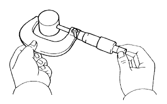 |
Using a micrometer, measure the lifter diameter.
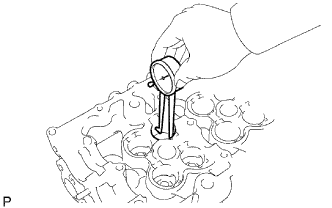 |
Using a caliper gauge, measure the lifter bore diameter of the cylinder head.
Measure the oil clearance by subtracting the lifter diameter measurement from the lifter bore diameter measurement.
| 13. INSPECT CAMSHAFT OIL CLEARANCE |
Clean the bearing caps and journals.
Check the bearings for flaking and scoring.
If the bearings are damaged, replace the bearing caps and cylinder head as a set.
Place the camshaft on the cylinder head.
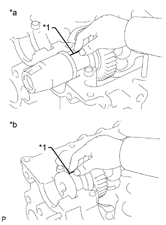 |
Lay a strip of Plastigage across each of the journals.
| *1 | Plastigage |
| *a | Intake Side |
| *b | Exhaust Side |
Install the bearing caps.
Remove the bearing caps.
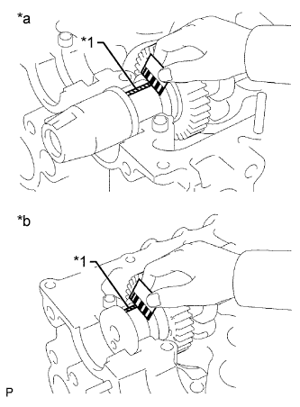 |
Measure the Plastigage at its widest point.
| *1 | Plastigage |
| *a | Intake Side |
| *b | Exhaust Side |
Completely remove the Plastigage.
Remove the camshaft.
| 14. INSPECT CAMSHAFT THRUST CLEARANCE |
Install the camshaft.
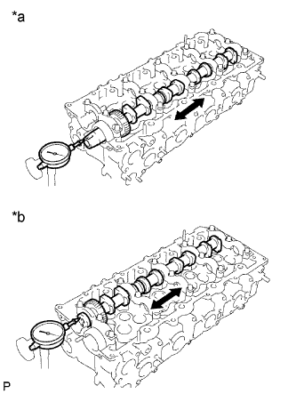 |
Using a dial indicator, measure the thrust clearance while moving the camshaft back and forth.
| *a | Intake Side |
| *b | Exhaust Side |
Remove the camshaft.