 |
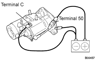
Perform the pull-in test.
Disconnect the field coil lead wire from terminal C.
Connect the battery to the magnetic switch as shown. Check that the clutch pinion gear moves outward.
STARTER > INSPECTION |
| 1. INSPECT STARTER ASSEMBLY |
|
Perform the pull-in test.
Disconnect the field coil lead wire from terminal C.
Connect the battery to the magnetic switch as shown. Check that the clutch pinion gear moves outward.
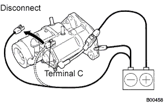 |
Perform the hold-in test.
When the battery is connected as above with the clutch pinion gear out, disconnect the negative (-) lead from terminal C. Check that the pinion gear remains out.
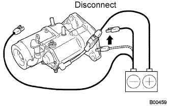 |
Inspect the clutch pinion gear return.
Disconnect the negative (-) lead from the starter body. Check that the clutch pinion gear returns inward.
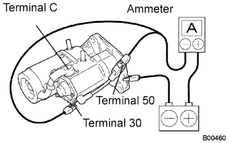 |
Perform the operation test without load.
Connect the field coil lead wire to terminal C.
Grip the starter in a vise.
Connect the battery and ammeter to the starter as shown.
Check that the ammeter displays the specified current.
| 2. INSPECT STARTER ARMATURE ASSEMBLY |
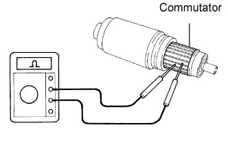 |
Inspect the commutator for an open circuit.
Measure the resistance between the segments of the commutator.
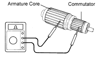 |
Inspect the commutator for a short circuit.
Using an ohmmeter, check that there is no resistance between the commutator and armature core.
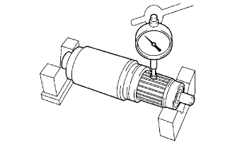 |
Inspect the commutator circle runout.
Place the armature on the V-blocks.
Using a dial indicator, measure the circle runout.
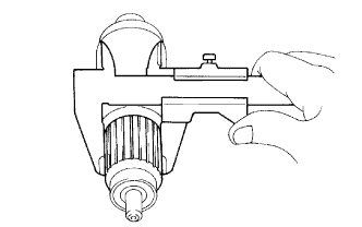 |
Using a vernier caliper, measure the commutator diameter.
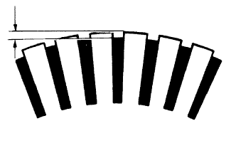 |
Measure the undercut depth of the commutator.
Inspect the bearings.
Check that the bearings rotate smoothly.
If necessary, replace them.
| 3. INSPECT STARTER YOKE ASSEMBLY |
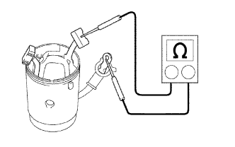 |
Inspect for an open circuit.
Measure the resistance between the terminal C wire and brushes.
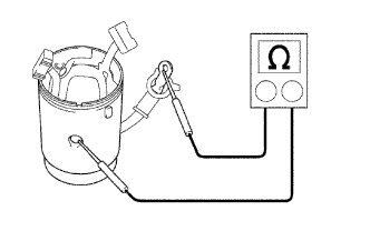 |
Inspect for a short circuit.
Measure the resistance between the terminal C wire and starter yoke body.
Measure the resistance between the brushes and starter yoke body.
| 4. INSPECT BRUSH |
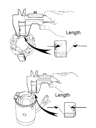 |
Using a vernier caliper, measure the brush length.
| 5. INSPECT STARTER BRUSH HOLDER ASSEMBLY |
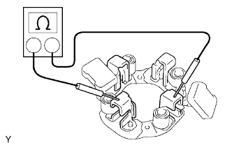 |
Measure the resistance between the positive and negative brush holders.
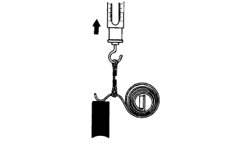 |
Using a pull scale, measure the brush spring load.
| 6. INSPECT STARTER CLUTCH SUB-ASSEMBLY |
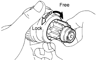 |
Check that the starter clutch cannot be rotated counterclockwise, and can be rotated clockwise.
| 7. INSPECT MAGNET STARTER SWITCH ASSEMBLY |
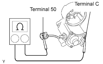 |
Inspect the pull-in coil.
Measure the resistance between terminals 50 and C.
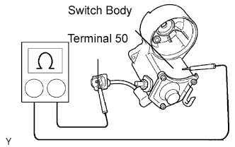 |
Inspect the hold-in coil.
Measure the resistance between terminal 50 and the switch body.