STEERING GEAR > REASSEMBLY |
| 1. INSTALL POWER STEERING CYLINDER TUBE OIL SEAL |
Install the spacer to the power steering rack housing.
Apply power steering fluid to the lip of a new power steering cylinder tube oil seal.
![]() |
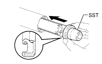
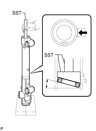
Install the power steering cylinder tube oil seal to the rack housing at an angle.
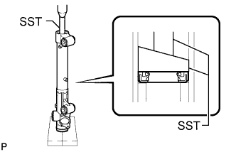
Using SST, push in the power steering cylinder tube oil seal by hand until the oil seal passes the 2 ports.
Install SST (09631-00200) to SST (09951-07360) upside down.
Using SST, push the power steering cylinder tube oil seal by hand so that it is level.
![]() |
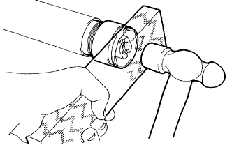
Using SST and a press, install the power steering cylinder tube oil seal.
| 2. INSTALL STEERING RACK PISTON RING |
![]() |
Coat a new O-ring with power steering fluid and install it on the steering rack.
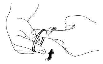
Stretch a new "teflon" ring with your fingers.
Coat the "teflon" ring with power steering fluid.
![]() |
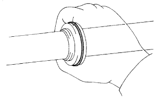
Install the "teflon" ring to the steering rack's groove. Grip the ring to press it into the groove.
| 3. INSTALL POWER STEERING RACK |
![]() |
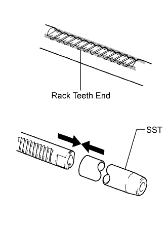
Apply grease to the rack teeth ends.
Install SST to the steering rack.
Coat SST with power steering fluid.
Install the steering rack to the rack housing.
Remove SST.
![]() |
Coat SST with power steering fluid.
Install SST to the steering rack opposite end.
Coat the lip of a new oil seal with power steering fluid. Using SST, install the oil seal to the steering rack.
Remove SST.
| 4. INSTALL CYLINDER END STOPPER |
Apply sealant to the stopper.
![]() |
Using a wooden block and hammer, tap in the stopper until it is tightly installed.
![]() |
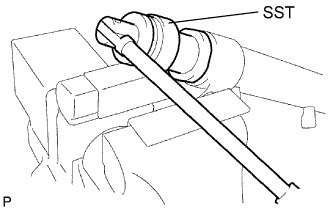
Using SST, tighten the stopper.
| 5. TEST AIR TIGHTNESS |
![]() |
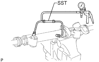
Install SST to the unions of the rack housing.
Apply 53.33 kPa (400 mmHg, 15.75 in.Hg) of vacuum for about 30 seconds.
Check that there is no change in the vacuum.
If there is a change in the vacuum, check the installation of the oil seals.
| 6. INSTALL POWER STEERING CONTROL VALVE |
![]() |
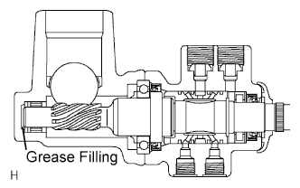
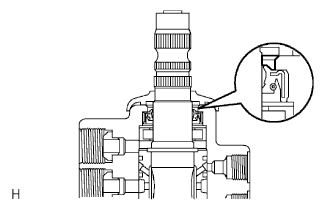
Apply molybdenum disulfide base grease to the needle roller bearing inside the rack housing shown in the illustration.
![]() |
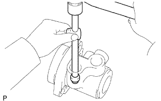
Using a plastic-faced hammer and a sliding handle, lightly tap in 2 new union seats.
![]() |
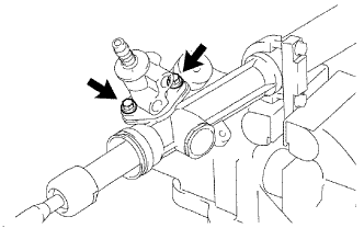
Install a control valve gasket and the control valve with the 2 bolts.
| 7. INSTALL RACK GUIDE |
Install the rack guide and spring.
Apply sealant to 2 or 3 threads of the rack guide spring cap.
![]() |
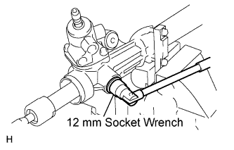
Using a 12 mm socket wrench, temporarily install the spring cap.
| 8. ADJUST TOTAL PRELOAD |
To prevent the steering rack teeth from damaging the lip of the oil seal, temporarily install the RH and LH rack ends.
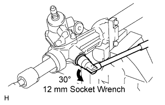
Using a 12 mm socket wrench, tighten the rack guide spring cap.
![]() |
Loosen the cap 30°.
![]() |
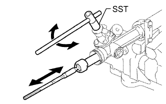
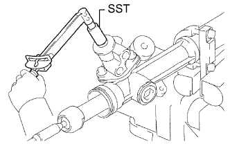
Using SST, turn the control valve shaft right and left 1 or 2 times. The rack end will move in and out.
Using a 12 mm socket wrench, loosen the cap until the rack guide spring does not function.
![]() |
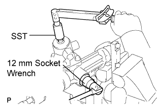
Using SST, a torque wrench and 12 mm socket wrench, tighten the cap until the preload is within the specification.
Apply sealant to 2 or 3 threads of the lock nut.
![]() |
Temporarily install the lock nut.
![]() |
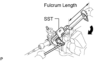
Using SST, recheck the total preload.
Remove the RH and LH rack ends.
| 9. INSPECT POWER STEERING RACK |
![]() |
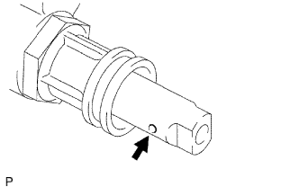
Insert a wire 20 mm (0.79 in.) into the vent hole of the steering rack, and ensure that the vent hole is not clogged with grease.
| 10. INSTALL STEERING RACK END SUB-ASSEMBLY |
![]() |
Install 2 new claw washers to the power steering rack while aligning the notch on the steering rack end with the claw.
Temporarily install the 2 steering rack ends to the power steering rack.
Fill up the ball joint of the steering rack ends with MP grease.
![]() |
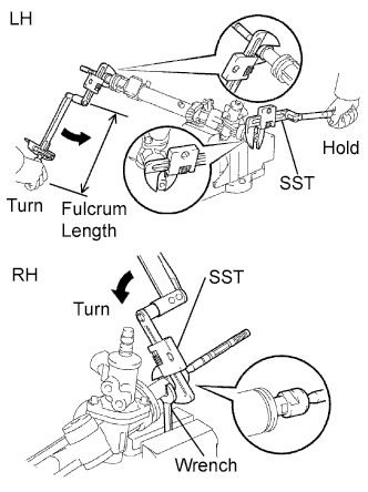
Using SST, install the power steering rack end (LH side) to the power steering rack.
Using SST and a wrench, install the power steering rack end (RH side) to the power steering rack.
![]() |
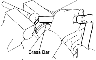
Using a brass bar and hammer, stake the 2 claw washers (LH and RH side).
| 11. INSTALL STEERING RACK BOOT LH |
Install the boot.
| 12. INSTALL STEERING RACK BOOT RH |
| 13. INSTALL STEERING RACK BOOT CLAMP LH |
![]() |
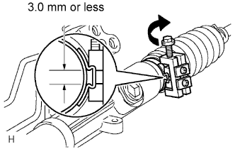
Using SST, tighten the rack boot clamp, as shown in the illustration.
| 14. INSTALL STEERING RACK BOOT CLAMP RH |
| 15. INSTALL STEERING RACK BOOT CLIP LH |
Using pliers, install the clip.
| 16. INSTALL STEERING RACK BOOT CLIP RH |
| 17. INSTALL POWER STEERING GEAR ASSEMBLY |
![]() |
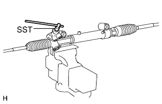
Using SST, check that the rack boot stretches smoothly when the control valve shaft is being rotated.
![]() |
Apply MP grease as shown in the illustration.
| 18. INSTALL STEERING TURN PRESSURE TUBE |
![]() |
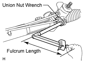
Apply power steering fluid to 2 new O-rings. Using union nut wrench, install the 2 O-rings and the LH turn pressure tube.
Apply power steering fluid to a new O-ring. Using union nut wrench, install the O-ring and one side of the RH turn pressure tube.
Apply power steering fluid to a new O-ring. Install the O-ring and the RH turn pressure tube.
| 19. INSTALL TIE ROD END SUB-ASSEMBLY LH |
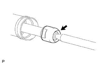
Screw the lock nut and tie rod end onto the rack end until the matchmarks are aligned.
After adjusting toe-in, torque the nut.
| 20. INSTALL TIE ROD END SUB-ASSEMBLY RH |
| 21. INSPECT AND ADJUST TIE ROD END SUB-ASSEMBLY (w/ VSC) |
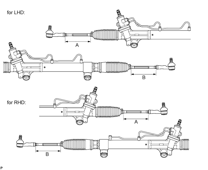
Adjust the tie rod end LH and RH so that distance A and B are within the specified ranges.

| Dimension | Control Range | |
| for LHD | A | 153.7 to 155.7 mm (6.06 to 6.12 in.) |
| B | ||
| for RHD | A | 153.7 to 155.7 mm (6.06 to 6.12 in.) |
| B |