STOP LIGHT SWITCH > INSTALLATION |
| 1. INSTALL STOP LIGHT SWITCH ASSEMBLY |
|
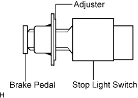
Install the adjuster to the support.
Insert the switch into the adjuster until it slightly touches the pedal.
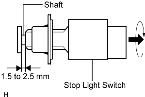 |
Turn the switch a quarter turn clockwise.
Check the switch clearance.
| 2. ADJUST STOP LIGHT SWITCH ASSEMBLY |
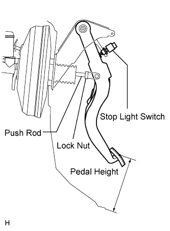 |
Check the pedal height.
| Model | Specified Condition |
| for LHD (Manual Transmission) | 152.9 to 162.9 mm (6.020 to 6.413 in.) |
| for LHD (Automatic Transmission) | 154.4 to 164.4 mm (6.079 to 6.472 in.) |
| for RHD (Manual Transmission) | 156.9 to 166.9 mm (6.177 to 6.571 in.) |
| for RHD (Automatic Transmission) | 158.1 to 168.1 mm (6.224 to 6.618 in.) |
Adjust the pedal height.
Disconnect the connector from the stop light switch.
Remove the switch.
Loosen the push rod clevis lock nut.
Adjust the pedal height by turning the push rod.
Tighten the lock nut.
|
Insert the switch into the adjuster until it slightly touches the pedal.
|
Turn the switch a quarter turn clockwise.
Connect the connector to the switch.
Check the switch clearance.
| 3. CONNECT CABLE TO NEGATIVE BATTERY TERMINAL |