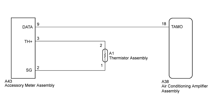
DTC 12 Ambient Temperature Sensor Circuit |
| DTC Code | DTC Detection Condition | Trouble Area |
| 12 | An open or short in ambient temperature sensor circuit |
|
| 1.CHECK ACCESSORY METER ASSEMBLY |
Check the difference between the ambient temperature value displayed on the accessory meter assembly and the actual ambient temperature.
|
| ||||
| OK | |
 |
| 2.CHECK HARNESS AND CONNECTOR (AIR CONDITIONING AMPLIFIER - ACCESSORY METER) |
Disconnect the A43 accessory meter assembly connector.
Disconnect the A38 air conditioning amplifier assembly connector.
Measure the resistance according to the value(s) in the table below.
| Tester Connection | Condition | Specified Condition |
| A43-9 (DATA) - A38-18 (TAMO) | Always | Below 1 Ω |
| A43-9 (DATA) - Body ground | Always | 10 kΩ or higher |
| Result | Proceed to |
| OK (When troubleshooting according to problem symptoms table.) | A |
| OK (When troubleshooting according to DTC.) | B |
| NG | C |
|
| ||||
|
| ||||
| A | ||
 | ||
| ||
| 3.INSPECT THERMISTOR ASSEMBLY |
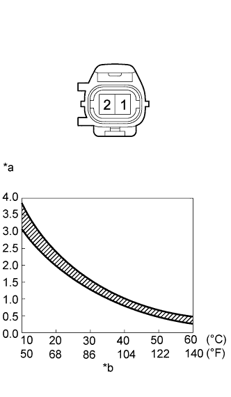 |
Remove the thermistor assembly (Click here).
Measure the resistance according to the value(s) in the table below.
| Tester Connection | Condition | Specified Condition |
| 1 - 2 | 10°C (50°F) | 3.00 to 3.73 kΩ |
| 15°C (59°F) | 2.45 to 2.88 kΩ | |
| 20°C (68°F) | 1.95 to 2.30 kΩ | |
| 25°C (77°F) | 1.60 to 1.80 kΩ | |
| 30°C (86°F) | 1.28 to 1.47 kΩ | |
| 35°C (95°F) | 1.00 to 1.22 kΩ | |
| 40°C (104°F) | 0.80 to 1.00 kΩ | |
| 45°C (113°F) | 0.65 to 0.85 kΩ | |
| 50°C (122°F) | 0.50 to 0.70 kΩ | |
| 55°C (131°F) | 0.44 to 0.60 kΩ | |
| 60°C (140°F) | 0.36 to 0.50 kΩ |
| *a | Resistance (kΩ) |
| *b | Temperature |
|
| ||||
| OK | |
|
| 4.CHECK HARNESS AND CONNECTOR (THERMISTOR - ACCESSORY METER) |
Disconnect the A43 accessory meter assembly connector.
Disconnect the A1 thermistor assembly connector.
Measure the resistance according to the value(s) in the table below.
| Tester Connection | Condition | Specified Condition |
| A43-3 (TH+) - A1-2 | Always | Below 1 Ω |
| A43-2 (SG) - A1-1 | ||
| A43-3 (TH+) - Body ground | Always | 10 kΩ or higher |
| A43-2 (SG) - Body ground |
|
| ||||
| OK | ||
| ||
| ||

