 |
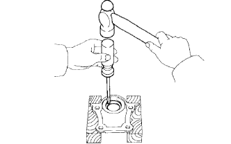
Using a screwdriver and hammer, tap out the oil seal.
- HINT:
- Tape the screwdriver tip.
CYLINDER HEAD > REPLACEMENT |
| 1. REMOVE NO. 2 OIL SEAL RETAINER OIL SEAL |
|
Using a screwdriver and hammer, tap out the oil seal.
| 2. REMOVE INTAKE VALVE GUIDE BUSH |
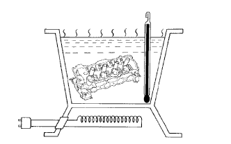 |
Gradually heat the cylinder head to approximately 80 to 100°C (176 to 212°F).
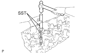 |
Using SST and a hammer, tap out the valve guide bushing.
| 3. REMOVE EXHAUST VALVE GUIDE BUSH |
|
Gradually heat the cylinder head to approximately 80 to 100°C (176 to 212°F).
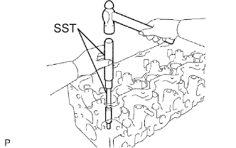 |
Using SST and a hammer, tap out the valve guide bushing.
| 4. INSTALL INTAKE VALVE GUIDE BUSH |
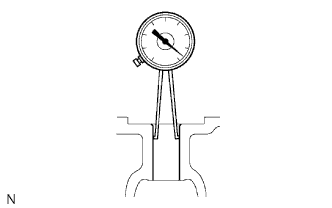 |
Using a caliper gauge, measure the bush bore diameter of the cylinder head.
Machine the bush bore diameter to between 13.054 and 13.075 mm (0.5139 to 0.5148 in.). Then select a new guide bush (STD or O/S 0.05).
| Bush Size | Specified Condition |
| STD | 13.004 to 13.025 mm (0.5120 to 0.5128 in.) |
| O/S 0.05 | 13.054 to 13.075 mm (0.5139 to 0.5148 in.) |
Gradually heat the cylinder head to approximately 80 to 100°C (176 to 212°F).
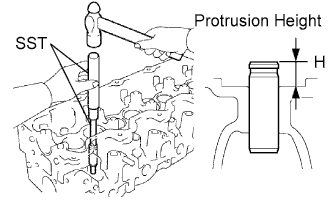 |
Using SST and a hammer, tap in a new guide bush to the specified protrusion height.
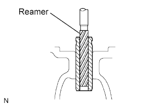 |
Using a sharp 8.0 mm reamer, ream the guide bush to obtain the standard specified clearance between the guide bush and valve stem.
| 5. INSTALL EXHAUST VALVE GUIDE BUSH |
|
Using a caliper gauge, measure the bush bore diameter of the cylinder head.
Machine the bush bore diameter to between 13.054 and 13.075 mm (0.5139 to 0.5148 in.). Then select a new guide bush (STD or O/S 0.05).
| Bush Size | Specified Condition |
| STD | 13.004 to 13.025 mm (0.5120 to 0.5128 in.) |
| O/S 0.05 | 13.054 to 13.075 mm (0.5139 to 0.5148 in.) |
Gradually heat the cylinder head to approximately 80 to 100°C (176 to 212°F).
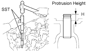 |
Using SST and a hammer, tap in a new guide bush to the specified protrusion height.
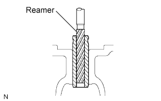 |
Using a sharp 8.0 mm reamer, ream the guide bush to obtain the standard specified clearance between the guide bush and valve stem.
| 6. INSTALL NO. 2 OIL SEAL RETAINER OIL SEAL |
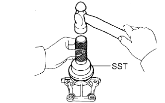 |
Using SST and a hammer, tap in a new oil seal until its surface is flush with the oil seal retainer edge.
Apply MP grease to the lip of the oil seal.