 |
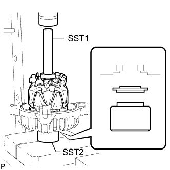
Set the spacer ring, drive end frame, generator rotor assembly and SST1 to SST2 as shown in the illustration.
- SST
- 09285-76010
09630-00014 (09631-00061)
GENERATOR > REASSEMBLY |
| 1. INSTALL GENERATOR ROTOR ASSEMBLY |
|
Set the spacer ring, drive end frame, generator rotor assembly and SST1 to SST2 as shown in the illustration.
Using SST1, SST2 and a press, slowly press the generator rotor into the drive end frame and spacer ring.
Temporarily install the generator pulley with clutch to the rotor shaft by hand.
| 2. INSTALL FITTING RING |
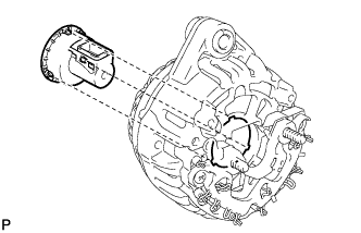 |
Align the 3 protrusions of the fitting ring with the 3 cutouts of the generator stator with rectifier and install the fitting ring.
| 3. INSTALL GENERATOR STATOR SUB-ASSEMBLY WITH RECTIFIER |
Align the key of the drive end frame with the keyway of the generator stator.
Install the stator with the 4 bolts.
| 4. INSTALL GENERATOR REGULATOR ASSEMBLY |
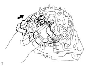 |
Push in the regulator by hand as shown in the illustration.
Install the regulator with the 3 screws.
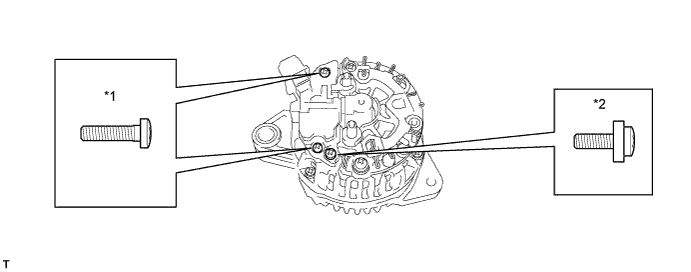
| *1 | Screw A |
| *2 | Screw B |
Install the protective tower.
| 5. INSTALL GENERATOR REAR END COVER |
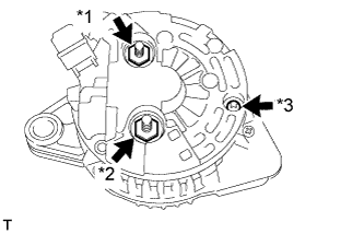 |
Install the rear end cover with the 2 nuts and screw.
| *1 | Nut A |
| *2 | Nut B |
| *3 | Screw |
Install the 2 terminal covers by turning them clockwise.
| 6. TIGHTEN GENERATOR PULLEY WITH CLUTCH |
Mount the generator assembly in a vise between aluminum plates.
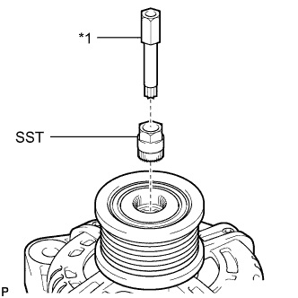 |
Set SST and an 8 mm bi-hexagon wrench to the pulley as shown in the illustration.
| *1 | 8mm Bi-hexagon Wrench |
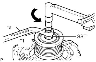 |
Hold SST in place, rotate the 8 mm bi-hexagon wrench counterclockwise, and tighten the generator pulley with clutch.
| *1 | 8mm Bi-hexagon Wrench |
| *a | Hold |
 | Turn |
| 7. INSTALL GENERATOR PULLEY CAP |
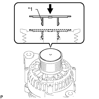 |
Install a new generator pulley cap.
| *1 | Cap Guide |