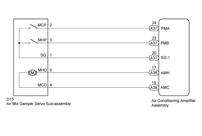
DTC 41 Air Mix Damper Control Servo Motor Circuit (Passenger Side) |
| DTC Code | DTC Detection Condition | Trouble Area |
| 41 | The air mix control damper position does not change when the air conditioning amplifier assembly operates the air mix damper servo sub-assembly. |
|
| 1.PERFORM ACTUATOR CHECK |
Warm up the engine.
Enter actuator check mode (Click here).
Place your hand in front of a vent and check that the air mix control damper position changes (the temperature of the air changes) according to the display code.
| Display Code | Air Mix Control Damper Position |
| 0 | COLD side (0% open) |
| 1 | COLD side (0% open) |
| 2 | COLD side (0% open) |
| 3 | COLD side (0% open) |
| 4 | COLD/HOT (50% open) |
| 5 | COLD/HOT (50% open) |
| 6 | HOT side (100% open) |
| 7 | HOT side (100% open) |
| 8 | HOT side (100% open) |
| 9 | HOT side (100% open) |
| Result | Proceed to |
| OK (When troubleshooting according to problem symptoms table.) | A |
| OK (When troubleshooting according to DTC.) | B |
| NG | C |
|
| ||||
|
| ||||
| A | ||
 | ||
| ||
| 2.CHECK HARNESS AND CONNECTOR (AIR MIX DAMPER SERVO - AIR CONDITIONING AMPLIFIER) |
Disconnect the D15 air mix damper servo sub-assembly connector.
Disconnect the A38 and A37 air conditioning amplifier assembly connectors.
Measure the resistance according to the value(s) in the table below.
| Tester Connection | Condition | Specified Condition |
| D15-5 (MHD) - A38-17 (AMH) | Always | Below 1 Ω |
| D15-4 (MCD) - A38-19 (AMC) | ||
| D15-3 (MHP) - A37-23 (PMB) | ||
| D15-2 (MCP) - A37-24 (PMA) | ||
| D15-1 (SG) - A37-20 (SG-1) | ||
| D15-1 (SG) - Body ground | Always | 10 kΩ or higher |
| D15-2 (MCP) - Body ground | ||
| D15-3 (MHP) - Body ground | ||
| D15-4 (MCD) - Body ground | ||
| D15-5 (MHD) - Body ground |
|
| ||||
| OK | |
 |
| 3.REPLACE AIR MIX DAMPER SERVO SUB-ASSEMBLY |
Temporally replace the air mix damper servo sub-assembly with a new or normally functioning one (Click here).
Check the air mix control damper operates normally.
|
| ||||
| OK | ||
| ||
| ||

