 |
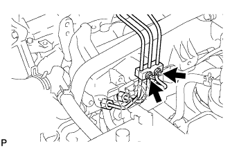
Remove the 2 nuts and No. 3 injection pipe clamp.
FUEL INJECTOR > REMOVAL |
| 1. DISCONNECT CABLE FROM NEGATIVE BATTERY TERMINAL |
| 2. REMOVE DIESEL THROTTLE BODY ASSEMBLY |
| 3. CHECK INJECTOR COMPENSATION CODE |
Read the injector compensation code .
Check that the compensation code of the installed injector is the same as the code registered in the ECM. If the code is the same, register the injector compensation code on the injector (Click here).
| 4. REMOVE NO. 1, NO. 2 AND NO. 3 INJECTION PIPE SUB-ASSEMBLY |
|
Remove the 2 nuts and No. 3 injection pipe clamp.
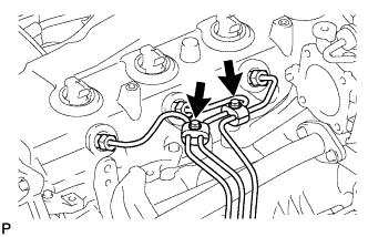 |
Remove the 2 bolts and 2 No. 2 injection pipe clamps.
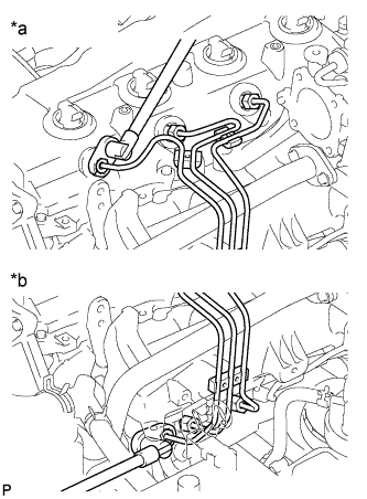 |
Using a 17 mm union nut wrench, loosen the union nuts and remove the No. 1, No. 2 and No. 3 injection pipes.
| *a | Injector Side |
| *b | Common Rail Side |
| 5. REMOVE NO. 2 INTAKE AIR CONNECTOR BRACKET |
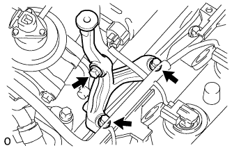 |
Remove the 3 bolts and No. 2 intake air connector bracket.
| 6. DISCONNECT NO. 3 WATER BY-PASS PIPE |
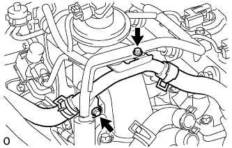 |
Remove the 2 bolts and disconnect the No. 3 water by-pass pipe with the wire harness.
| 7. REMOVE ELECTRIC VACUUM REGULATING VALVE ASSEMBLY (for EGR) |
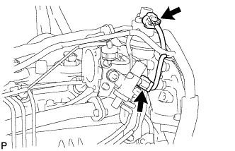 |
Disconnect the 2 connectors.
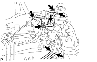 |
Disconnect the 6 vacuum hoses.
Remove the bolt and No. 1 gas filter with gas filter bracket.
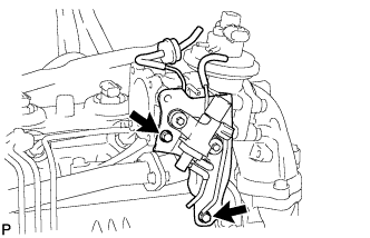 |
Remove the 2 bolts and electric vacuum regulating valve.
| 8. REMOVE NO. 2 INTAKE AIR CONNECTOR |
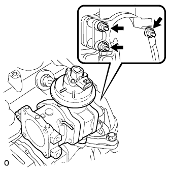 |
Remove the 3 nuts, No. 2 intake air connector and gasket.
| 9. REMOVE INTAKE AIR CONNECTOR |
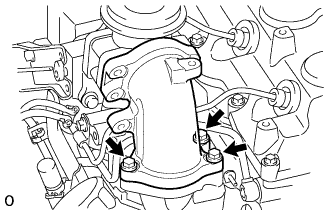 |
Remove the 3 bolts, intake air connector and 2 gaskets.
| 10. REMOVE ELECTRIC EGR CONTROL VALVE ASSEMBLY WITH NO. 1 EGR PIPE SUB-ASSEMBLY |
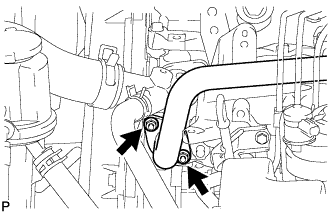 |
Remove the 2 nuts, electric EGR control valve with No. 1 EGR pipe and gasket.
| 11. REMOVE NO. 4 INJECTION PIPE SUB-ASSEMBLY |
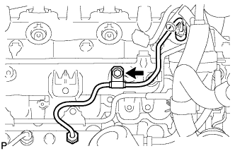 |
Remove the bolt and disconnect the injection pipe clamp.
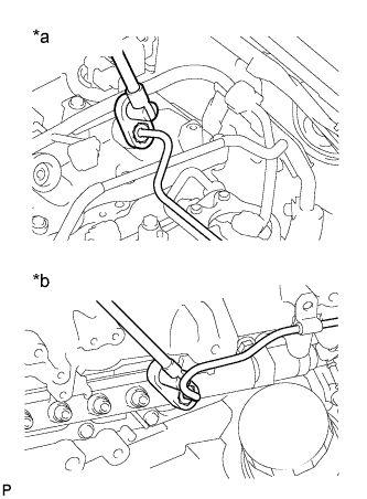 |
Using a 17 mm union nut wrench, loosen the union nuts and remove the No. 4 injection pipe.
| *a | Injector Side |
| *b | Common Rail Side |
| 12. REMOVE NO. 2 NOZZLE LEAKAGE PIPE ASSEMBLY |
Disconnect the 3 fuel hoses.
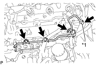 |
Remove the union bolt, 3 bolts, No. 2 nozzle leakage pipe and gasket.
| *1 | Union Bolt |
| 13. REMOVE CYLINDER HEAD COVER SUB-ASSEMBLY |
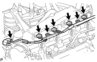 |
Remove the 3 bolts and disconnect the 4 connectors.
Disconnect the ventilation hose.
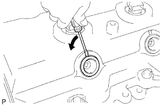 |
Using a small screwdriver, remove the nozzle holder seal by prying between the nozzle holder seal and the cutout part of the cylinder head cover.
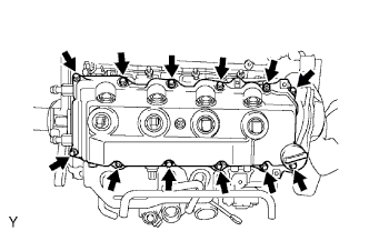 |
Remove the 10 bolts, 2 nuts, cylinder head cover and cylinder head cover gasket.
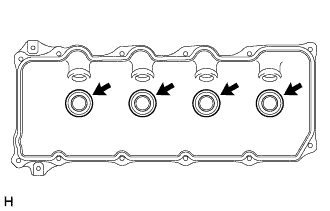 |
Remove the 4 No. 3 cylinder head cover gaskets from the cylinder head cover.
| 14. REMOVE INJECTOR ASSEMBLY |
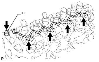 |
Remove the union bolt, 4 injector hollow screws, 5 gaskets and nozzle leakage pipe.
| *1 | Union Bolt |
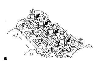 |
Remove the 4 bolts, 4 washers, 4 No. 1 nozzle holder clamps and 4 injectors.
Remove the O-ring from each injector.
Remove the 4 injection nozzle seats from the cylinder head.