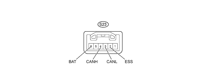
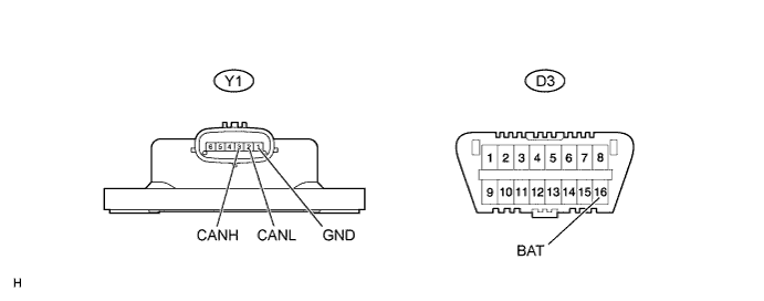
CAN COMMUNICATION SYSTEM (w/ VSC) > TERMINALS OF ECU |
| DISCONNECT CABLE FROM NEGATIVE BATTERY TERMINAL |
Disconnect the cable from the negative (-) battery terminal before measuring the resistances of the main wire and the branch wire.
| JUNCTION CONNECTOR |
NO. 1 JUNCTION CONNECTOR
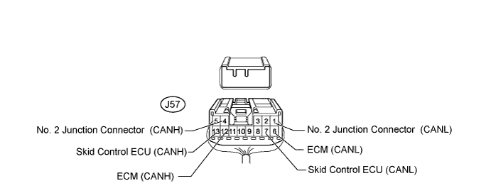
| No. 1 Junction Connector | Wiring Color | Connect to |
| J57-4 (CANH) | B | No. 2 junction connector |
| J57-1 (CANL) | W | |
| J57-12 (CANH) | B | ECM |
| J57-6 (CANL) | W | |
| J57-13 (CANH) | R | Skid control ECU |
| J57-7 (CANL) | W |
NO. 2 JUNCTION CONNECTOR
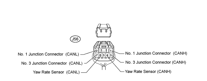
| No. 2 Junction Connector | Wiring Color | Connect to |
| J56-1 (CANH) | B | No. 1 junction connector |
| J56-2 (CANL) | W | |
| J56-3 (CANH) | B | No. 3 junction connector |
| J56-7 (CANL) | W | |
| J56-4 (CANH) | R | Yaw rate sensor |
| J56-6 (CANL) | W |
NO. 3 JUNCTION CONNECTOR
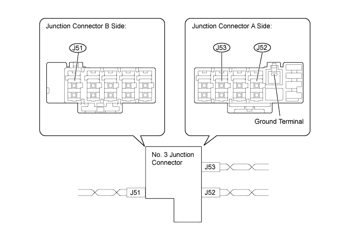
| Junction Connector A Side | Color (CANH Side) | Color (CANL Side) |
| No. 2 junction connector (J52) | B | W |
| Steering angle sensor (J53) | R | W |
| Junction Connector B Side | Color (CANH Side) | Color (CANL Side) |
| DLC3 (J51) | R | W |
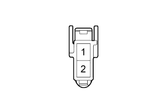
| TERMINALS OF CONNECTORS FOR JUNCTION CONNECTOR |
![]() |
| Terminal No. | Symbol |
| 1 | CANL |
| 2 | CANH |
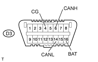
| CHECK DLC3 |
![]() |
Disconnect the cable from the negative (-) battery terminal before measuring the resistances of the main wire and the branch wire.
Measure the resistance according to the value(s) in the table below.
| Terminal No. (Symbols) | Wiring Color | Switch Condition | Specified Condition |
| D3-6 (CANH) - D3-14 (CANL) | R - W | Ignition switch off | 54 to 69 Ω |
| D3-6 (CANH) - D3-4 (CG) | R - G | Ignition switch off | 200 Ω or higher |
| D3-14 (CANL) - D3-4 (CG) | W - G | Ignition switch off | 200 Ω or higher |
| D3-6 (CANH) - D3-16 (BAT) | R - G | Ignition switch off | 6 kΩ or higher |
| D3-14 (CANL) - D3-16 (BAT) | W - G | Ignition switch off | 6 kΩ or higher |
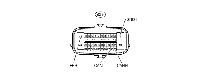
| CHECK SKID CONTROL ECU |

Disconnect the S25 ECU connector.
Measure the resistance according to the value(s) in the table below.
| Terminal No. (Symbols) | Wiring Color | Switch Condition | Specified Condition |
| S25-25 (CANH) - S25-14 (CANL) | B - W | Ignition switch off | 54 to 69 Ω |
| S25-25 (CANH) - S25-1 (GND1) | B - W-B | Ignition switch off | 200 Ω or higher |
| S25-14 (CANL) - S25-1 (GND1) | W - W-B | Ignition switch off | 200 Ω or higher |
| S25-25 (CANH) - S25-12 (+BS) | B - W-R | Ignition switch off | 6 kΩ or higher |
| S25-14 (CANL) - S25-12 (+BS) | W - W-R | Ignition switch off | 6 kΩ or higher |
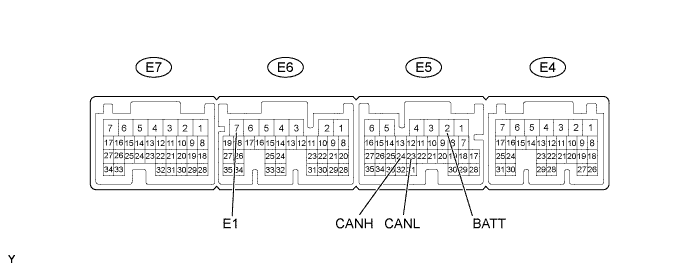
| CHECK ECM (for 1KD-FTV, 2KD-FTV) |

Disconnect the E5 and E6 ECM connectors.
Measure the resistance according to the value(s) in the table below.
| Terminal No. (Symbols) | Wiring Color | Switch Condition | Specified Condition |
| E5-24 (CANH) - E5-23 (CANL) | B - W | Ignition switch off | 108 to 132 Ω |
| E5-24 (CANH) - E6-7 (E1) | B - BR | Ignition switch off | 200 Ω or higher |
| E5-23 (CANL) - E6-7 (E1) | W - BR | Ignition switch off | 200 Ω or higher |
| E5-24 (CANH) - E5-2 (BATT) | B - L | Ignition switch off | 6 kΩ or higher |
| E5-23 (CANL) - E5-2 (BATT) | W - L | Ignition switch off | 6 kΩ or higher |
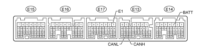
| CHECK ECM (for 1GR-FE) |

Disconnect the E13, E14 and E17 ECM connectors.
Measure the resistance according to the value(s) in the table below.
| Terminal No. (Symbols) | Wiring Color | Switch Condition | Specified Condition |
| E13-33 (CANH) - E13-34 (CANL) | B - W | Ignition switch off | 108 to 132 Ω |
| E13-33 (CANH) - E17-1 (E1) | B - BR | Ignition switch off | 200 Ω or higher |
| E13-34 (CANL) - E17-1 (E1) | W - BR | Ignition switch off | 200 Ω or higher |
| E13-33 (CANH) - E14-3 (BATT) | B - L | Ignition switch off | 6 kΩ or higher |
| E13-34 (CANL) - E14-3 (BATT) | W - L | Ignition switch off | 6 kΩ or higher |
| CHECK STEERING ANGLE SENSOR |

Disconnect the S23 sensor connector.
Measure the resistance according to the value(s) in the table below.
| Terminal No. (Symbols) | Wiring Color | Switch Condition | Specified Condition |
| S23-4 (CANH) - S23-3 (CANL) | R - W | Ignition switch off | 54 to 69 Ω |
| S23-4 (CANH) - S23-2 (ESS) | R - W-B | Ignition switch off | 200 Ω or higher |
| S23-3 (CANL) - S23-2 (ESS) | W - W-B | Ignition switch off | 200 Ω or higher |
| S23-4 (CANH) - S23-6 (BAT) | R - B | Ignition switch off | 6 kΩ or higher |
| S23-3 (CANL) - S23-6 (BAT) | W - B | Ignition switch off | 6 kΩ or higher |
| CHECK YAW RATE SENSOR |

Disconnect the Y1 sensor connector.
Measure the resistance according to the value(s) in the table below.
| Terminal No. (Symbols) | Wiring Color | Switch Condition | Specified Condition |
| Y1-3 (CANH) - Y1-2 (CANL) | B - W | Ignition switch off | 54 to 69 Ω |
| Y1-3 (CANH) - Y1-1 (GND) | B - W-B | Ignition switch off | 200 Ω or higher |
| Y1-2 (CANL) - Y1-1 (GND) | W - W-B | Ignition switch off | 200 Ω or higher |
| Y1-3 (CANH) - D3-16 (BAT) | B - G | Ignition switch off | 6 kΩ or higher |
| Y1-2 (CANL) - D3-16 (BAT) | W - G | Ignition switch off | 6 kΩ or higher |