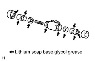
The bleeder plug will be tightened to a torque specification in the "bleed air from brake line" procedures.
Install the cap.
3.
INSTALL REAR WHEEL BRAKE CYLINDER ASSEMBLY LH
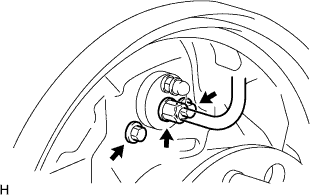
Install the cylinder with the 2 bolts.
Torque:
12 N*m{
117 kgf*cm
, 8 ft.*lbf
}
Using a union nut wrench, connect the brake line.
Torque:
15 N*m{
155 kgf*cm
, 11 ft.*lbf
}
NOTICE:
Use the formula to calculate special torque values for situations where a union nut wrench is combined with a torque wrench (Click here).
4.
APPLY HIGH TEMPERATURE GREASE
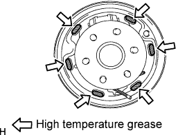
Apply high temperature grease to the surface of the backing plate where the shoe will be attached.
Apply high temperature grease to the anchor block plate and cable setting area.
5.
INSTALL REAR BRAKE PARKING BRAKE SHOE LEVER SUB-ASSEMBLY
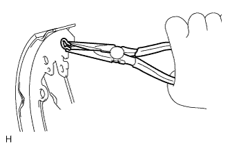
Using needle-nose pliers, install the lever with a new C-washer.
6.
INSTALL BRAKE SHOES
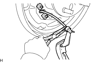
Using needle-nose pliers, connect the No. 3 parking brake cable to the parking brake shoe lever.
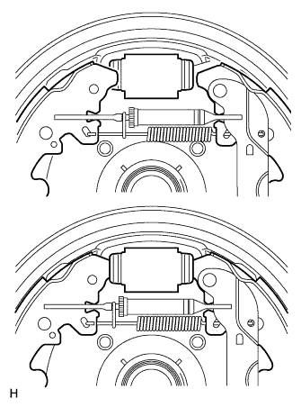
Install the strut set and return spring to the shoe.
Attach the support clip to exposed threads of the strut set.
NOTICE:
The support clip shall not contact the adjuster nut.
Using needle-nose pliers, hook the support clip around the spring.
NOTICE:
Be careful not to damage the spring.
Install the front and rear brake shoes.
Move one of the shoes upward and install the shoe tension spring.
Install the shoe front or rear side to the cylinder. Then install the other side of the shoe to the other side of the cylinder.
HINT:
After one side of the shoe is installed to the cylinder, hold that side of the shoe steady. Then widen the opening of the shoe by pulling the other side of the shoe outward and install it to the other side of the cylinder.
NOTICE:
Be careful not to damage the cylinder dust boot.
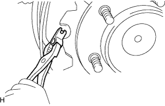
Using pliers, install the front brake shoe, rear brake shoe, pins and shoe hold down springs.
7.
INSTALL REAR BRAKE AUTOMATIC ADJUST LEVER LH
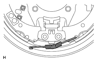
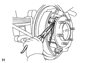
Using needle-nose pliers, install the lever and lever tension spring.
8.
CHECK REAR BRAKE DRUM INSTALLATION
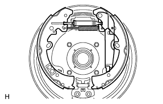
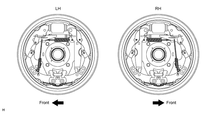
Check that each part is installed properly.
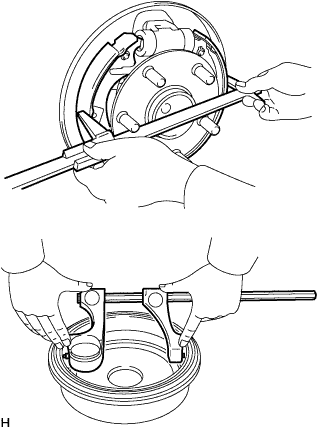
Measure the inside diameter of the drum and the diameter of the shoes. Check that the difference between the diameters is the correct shoe clearance.
Standard shoe clearance:
0.6 mm (0.0236 in.)
NOTICE:
There should be no oil or grease on the contact surfaces of the shoe lining and drum.