ADJUSTMENT
Removal / installation · Vehicles built Aug 2012 – Jul 2013
Versions by build date: Jun 2011 – Jul 2012 Aug 2012 – Jul 2013 from Aug 2013
- NOTICE:
- When replacing the injectors (including shuffling the injectors between the cylinders), common rail or cylinder head, it is necessary to replace the injection pipes with new ones.
- When replacing the fuel supply pump, common rail, cylinder block, cylinder head, cylinder head gasket or timing gear case, it is necessary to replace the fuel inlet pipe with a new one.
- After removing the injection pipes, clean them with a brush and compressed air.
- When replacing the injectors (including shuffling the injectors between the cylinders), common rail or cylinder head, it is necessary to replace the injection pipes with new ones.
- HINT:
- The injectors do not need to be removed when inspecting the valve clearance.
| 1. REMOVE CYLINDER HEAD COVER SUB-ASSEMBLY |

| 2. SET NO. 1 CYLINDER TO TDC/COMPRESSION |
Align the matchmarks of the crankshaft pulley and timing gear case cover by rotating the crankshaft clockwise.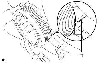

Text in Illustration *1
Matchmark
- HINT:
- Make sure that both cam lobes (intake side and exhaust side) of the No. 1 cylinder face upward.
| 3. INSPECT VALVE CLEARANCE |
Check only the valves indicated.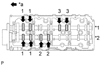
Using a feeler gauge, measure the clearance between the valve lifter and camshaft.
- Standard Valve Clearance (Cold):
Item
Specified Condition
Intake
0.2 to 0.3 mm (0.008 to 0.012 in.)
Exhaust
0.35 to 0.45 mm (0.014 to 0.018 in.)
Write down any valve clearance measurements that are not within the specified range. These measurements will be used later to determine the size of the adjustment lifter to be installed.Text in Illustration *1
Exhaust
*2
Intake
*a
Front
Turn the crankshaft 360° to set the No. 4 cylinder to TDC/compression.
Check only the valves indicated.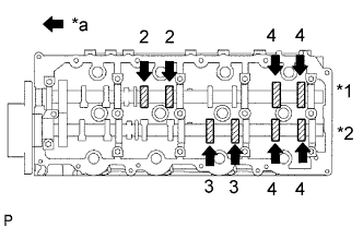
Using a feeler gauge, measure the clearance between the valve lifter and camshaft.
- Standard Valve Clearance (Cold):
Item
Specified Condition
Intake
0.2 to 0.3 mm (0.008 to 0.012 in.)
Exhaust
0.35 to 0.45 mm (0.014 to 0.018 in.)
Write down any valve clearance measurements that are not within the specified range. These measurements will be used later to determine the size of the adjustment lifter to be installed.Text in Illustration *1
Exhaust
*2
Intake
*a
Front
| 4. ADJUST VALVE CLEARANCE |
Remove the injector.
Remove the timing belt.
Remove the camshaft timing pulley.
Remove the No. 2 timing belt cover.
Remove the camshafts.
Remove the valve lifters.
Using a micrometer, measure the thickness of the removed lifter.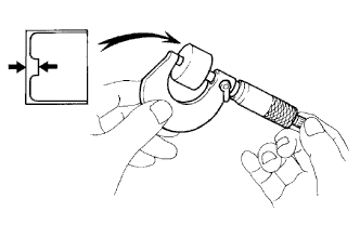
Calculate the thickness of a new lifter so that the valve clearance is within the specified range.
A
B
C
New lifter thickness
Used lifter thickness
Measured valve clearance
- New lifter thickness:
- Intake: A = B + (C - 0.25 mm (0.0098 in.))
- Exhaust: A = B + (C - 0.40 mm (0.0157 in.))
Select a new lifter with a thickness as close as possible to the calculated values.
- HINT:
- Valve lifters are available in 35 sizes in increments of 0.02 mm (0.0008 in.), from 5.06 mm (0.1992 in.) to 5.74 mm (0.2260 in.).
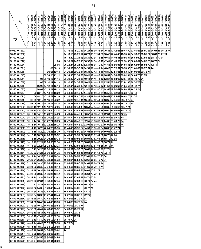
Text in Illustration *1
Valve Lifter Selection Chart (Intake)
*2
Installed lifter thickness mm (in.)
*3
Measured clearance mm (in.)
-
-
- Standard intake valve clearance (Cold):
- 0.2 to 0.3 mm (0.008 to 0.012 in.)
- EXAMPLE:
- A 5.25 mm (0.207 in.) lifter is installed, and the measured clearance is 0.4 mm (0.0157 in.). Replace the 5.25 mm (0.207 in.) lifter with a No. 40 lifter.
- New Lifter Thickness:
Lifter No.
Specified Condition
Lifter No.
Specified Condition
Lifter No.
Specified Condition
06
5.06 mm (0.1992 in.)
30
5.30 mm (0.2087 in.)
54
5.54 mm (0.2181 in.)
08
5.08 mm (0.2000 in.)
32
5.32 mm (0.2094 in.)
56
5.56 mm (0.2189 in.)
10
5.10 mm (0.2008 in.)
34
5.34 mm (0.2102 in.)
58
5.58 mm (0.2197 in.)
12
5.12 mm (0.2016 in.)
36
5.36 mm (0.2110 in.)
60
5.60 mm (0.2205 in.)
14
5.14 mm (0.2024 in.)
38
5.38 mm (0.2118 in.)
62
5.62 mm (0.2213 in.)
16
5.16 mm (0.2031 in.)
40
5.40 mm (0.2126 in.)
64
5.64 mm (0.2220 in.)
18
5.18 mm (0.2039 in.)
42
5.42 mm (0.2134 in.)
66
5.66 mm (0.2228 in.)
20
5.20 mm (0.2047 in.)
44
5.44 mm (0.2142 in.)
68
5.68 mm (0.2236 in.)
22
5.22 mm (0.2055 in.)
46
5.46 mm (0.2150 in.)
70
5.70 mm (0.2244 in.)
24
5.24 mm (0.2063 in.)
48
5.48 mm (0.2157 in.)
72
5.72 mm (0.2252 in.)
26
5.26 mm (0.2071 in.)
50
5.50 mm (0.2165 in.)
74
5.74 mm (0.2260 in.)
28
5.28 mm (0.2079 in.)
52
5.52 mm (0.2173 in.)
-
-
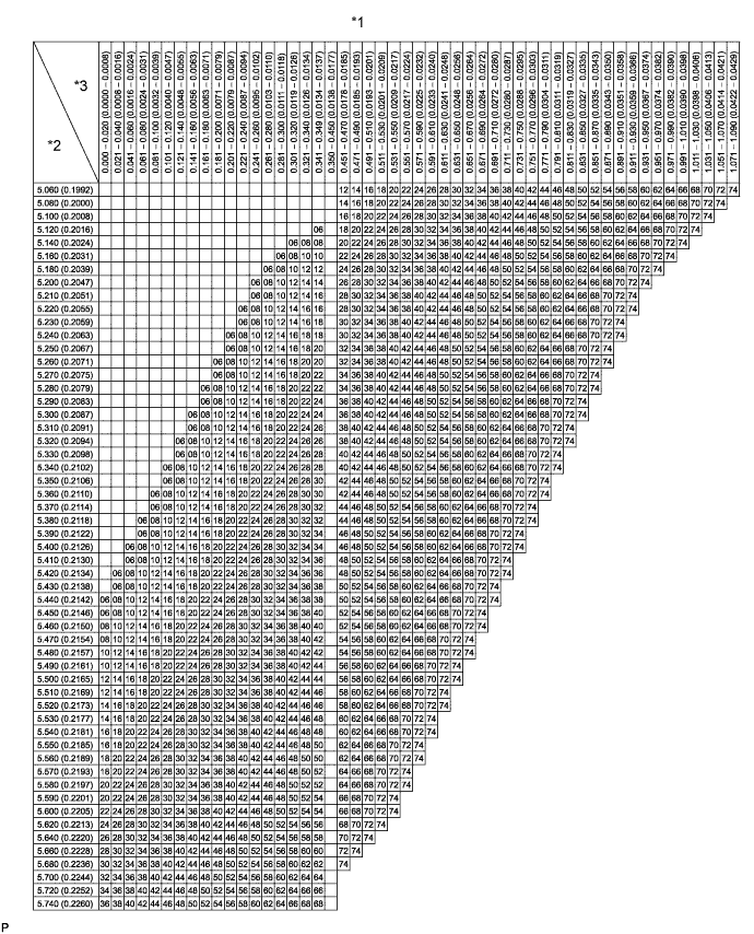
Text in Illustration *1
Valve Lifter Selection Chart (Exhaust)
*2
Installed lifter thickness mm (in.)
*3
Measured clearance mm (in.)
-
-
- Standard exhaust valve clearance (Cold):
- 0.35 to 0.45 mm (0.014 to 0.018 in.)
- EXAMPLE:
- A 5.34 mm (0.210 in.) lifter is installed, and the measured clearance is 0.48 mm (0.0189 in.). Replace the 5.34 mm (0.210 in.) lifter with a No. 42 lifter.
- New Lifter Thickness:
Lifter No.
Specified Condition
Lifter No.
Specified Condition
Lifter No.
Specified Condition
06
5.06 mm (0.1992 in.)
30
5.30 mm (0.2087 in.)
54
5.54 mm (0.2181 in.)
08
5.08 mm (0.2000 in.)
32
5.32 mm (0.2094 in.)
56
5.56 mm (0.2189 in.)
10
5.10 mm (0.2008 in.)
34
5.34 mm (0.2102 in.)
58
5.58 mm (0.2197 in.)
12
5.12 mm (0.2016 in.)
36
5.36 mm (0.2110 in.)
60
5.60 mm (0.2205 in.)
14
5.14 mm (0.2024 in.)
38
5.38 mm (0.2118 in.)
62
5.62 mm (0.2213 in.)
16
5.16 mm (0.2031 in.)
40
5.40 mm (0.2126 in.)
64
5.64 mm (0.2220 in.)
18
5.18 mm (0.2039 in.)
42
5.42 mm (0.2134 in.)
66
5.66 mm (0.2228 in.)
20
5.20 mm (0.2047 in.)
44
5.44 mm (0.2142 in.)
68
5.68 mm (0.2236 in.)
22
5.22 mm (0.2055 in.)
46
5.46 mm (0.2150 in.)
70
5.70 mm (0.2244 in.)
24
5.24 mm (0.2063 in.)
48
5.48 mm (0.2157 in.)
72
5.72 mm (0.2252 in.)
26
5.26 mm (0.2071 in.)
50
5.50 mm (0.2165 in.)
74
5.74 mm (0.2260 in.)
28
5.28 mm (0.2079 in.)
52
5.52 mm (0.2173 in.)
-
-
Install the selected valve lifters.
Install the camshafts.
Install the No. 2 timing belt cover.
Install the camshaft timing pulley.
Install the timing belt.
Install the fuel injector.
| 5. INSTALL CYLINDER HEAD COVER SUB-ASSEMBLY |
| 6. INSPECT FOR COOLANT LEAK |
| 7. BLEED AIR FROM FUEL SYSTEM |
Using the hand pump mounted on the fuel filter cap, bleed the air from the fuel system. Continue pumping until the pump resistance increases.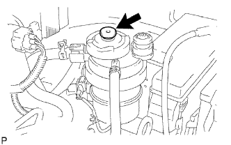
- NOTICE:
- Hand pump pumping speed: Max. 2 strokes/ sec.
- The hand pump must be pushed with a full stroke during pumping.
- When the fuel pressure at the supply pump inlet port reaches a saturated pressure, the hand pump resistance increases.
- If pumping is interrupted during the air bleeding process, fuel in the fuel line may return to the fuel tank. Continue pumping until the hand pump resistance increases.
- If the hand pump resistance does not increase despite consecutively pumping 200 times or more, there may be a fuel leak between the fuel tank and fuel filter, the hand pump may be malfunctioning, or the vehicle may have run out of fuel.
- If air bleeding using the hand pump is incomplete, the common rail pressure does not rise to the pressure range necessary for normal use, and the engine cannot be started.
- Hand pump pumping speed: Max. 2 strokes/ sec.
Check if the engine starts.
- NOTICE:
- Even if air bleeding using the hand pump has been completed, the starter may need to be cranked for 10 seconds or more to start the engine.
- Do not crank the engine continuously for more than 20 seconds. The battery may be discharged.
- Use a fully-charged battery.
- Even if air bleeding using the hand pump has been completed, the starter may need to be cranked for 10 seconds or more to start the engine.
When the engine can be started, proceed to the next step.
If the engine cannot be started, bleed the air again using the hand pump until the hand pump resistance increases (refer to the procedures above). Then start the engine.
Turn the ignition switch off.
Connect the intelligent tester to the DLC3.
Turn the ignition switch to ON and turn the intelligent tester on.
Clear the DTCs (Click here).
Start the engine.*1
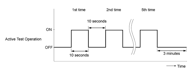
Enter the following menus: Powertrain / Engine and ECT / Active Test / Test the Fuel Leak.*2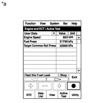
Text in Illustration *a
Reference
(Active Test Operation)
Perform the following test 5 times with on/off intervals of 10 seconds: Active Test / Test the Fuel Leak.*3
Allow the engine to idle for 3 minutes or more after performing the Active Test for the fifth time.
- HINT:
- When the Active Test "Test the Fuel Leak" is used to change the pump control mode, the actual fuel pressure inside the common rail drops below the target fuel pressure when the Active Test is off, but this is normal and does not indicate a pump malfunction.
Enter the following menus: Powertrain / Engine and ECT / DTC.
Read Current DTCs.
Clear the DTCs (Click here).
- HINT:
- It is necessary to clear the DTCs, as DTC P1604 or P1605 may be stored when air is bled from the fuel system after replacing or repairing fuel system parts.
Repeat steps *1 to *3.
Enter the following menus: Powertrain / Engine and ECT / DTC.
Read Current DTCs.
- OK:
- No DTCs are output.
| 8. INSPECT FOR FUEL LEAK |
Perform the Active Test.
Connect the intelligent tester to the DLC3.
Turn the ignition switch to ON.
Turn the intelligent tester on.
Enter the following menus: Powertrain / Engine and ECT / Active Test.
Perform the Active Test.
Intelligent Tester Display
Test Part
Control Range
Diagnostic Note
Test the Fuel Leak
Pressurize common rail interior and check for fuel leaks
Stop/Start
- The fuel pressure inside the common rail increases to the specified value and the engine speed increases to 2000 rpm when the Active Test is performed.
- The above conditions are maintained while the Active Test is being performed.
- The fuel pressure inside the common rail increases to the specified value and the engine speed increases to 2000 rpm when the Active Test is performed.
| 9. INSPECT FOR OIL LEAK |
Start the engine. Make sure that there are no oil leaks from the areas that were worked on.