REASSEMBLY
Removal / installation · Vehicles built from Jun 2011
| 1. INSTALL STUD BOLT |

- HINT:
- If a stud bolt is deformed or its threads are damaged, replace it.
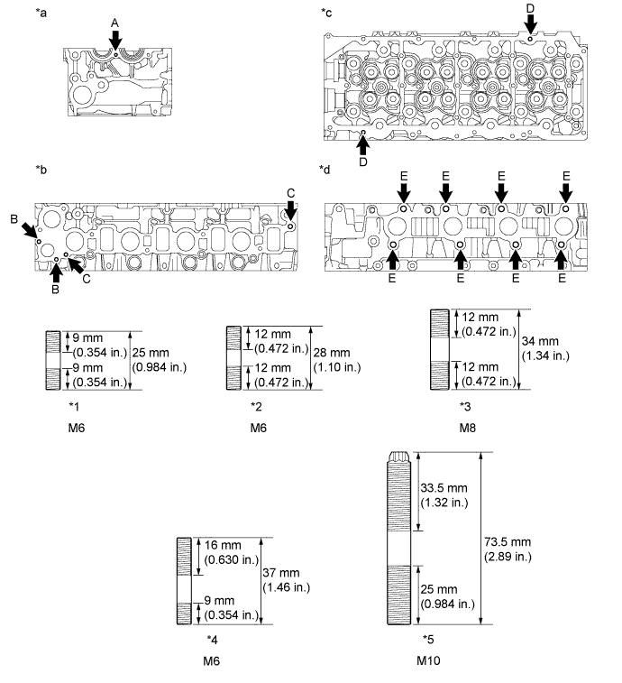
Install the stud bolts.
- Torque:
- for stud bolt A and D:
- 5.0 N*m{ 51 kgf*cm , 44 in.*lbf }
- for stud bolt B:
- 7.0 N*m{ 71 kgf*cm , 62 in.*lbf }
- for stud bolt C:
- 15 N*m{ 153 kgf*cm , 11 ft.*lbf }
- for stud bolt E:
- 20 N*m{ 204 kgf*cm , 15 ft.*lbf }

Text in Illustration *1
Stud Bolt A
*2
Stud Bolt B
*3
Stud Bolt C
*4
Stud Bolt D
*5
Stud Bolt E
-
-
*a
Front Side
*b
Intake Manifold Side
*c
Cylinder Head Cover Side
*d
Exhaust Manifold Side
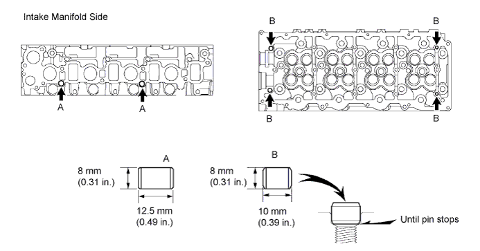
| 2. INSTALL RING PIN |
| 3. INSTALL STRAIGHT SCREW PLUG |
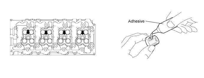
Apply an adhesive to the end of the screw plug.
- Adhesive:
- Toyota Genuine Adhesive 1324, Three Bond 1324 or equivalent
Using a 6 mm hexagon wrench, install the screw plug.
- Torque:
- 25 N*m{ 255 kgf*cm , 18 ft.*lbf }
| 4. INSTALL SEMICIRCULAR PLUG |
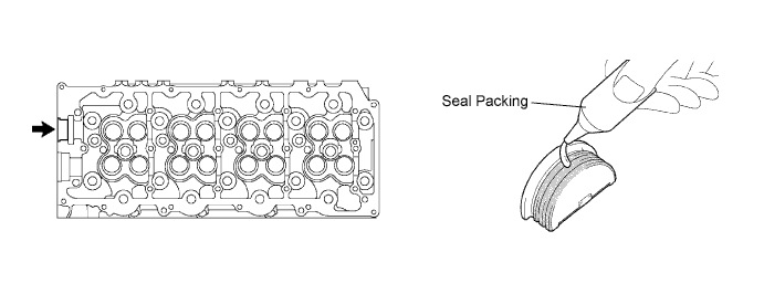
Remove any old packing (FIPG) material.
Apply seal packing to the oil seal retainer as shown in the illustration.
- Seal packing:
- Toyota Genuine Seal Packing Black, Three Bond 1207B or equivalent
- NOTICE:
- The semicircular plug must be installed within 3 minute from the completion of applying the seal packing.
- Prevent FIPG from being stuck to the camshaft thrust groove.
- The semicircular plug must be installed within 3 minute from the completion of applying the seal packing.
Install the semicircular plug to the cylinder head.
| 5. INSTALL INTAKE VALVE |
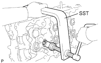 |
Install the valve, spring seat, compression spring and spring retainer.
Using SST, compress the compression spring and place the 2 valve spring retainer locks around the valve stem.
- SST
- 09202-70020
(09202-00020)
Using a plastic-faced hammer, lightly tap the valve stem tip to assure a proper fit.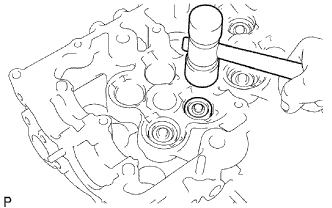
- NOTICE:
- Be careful not do damage the valve stem tip.
| 6. INSTALL EXHAUST VALVE |
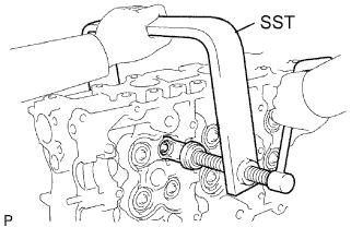 |
Install the valve, spring seat, compression spring and spring retainer.
Using SST, compress the compression spring and place the 2 valve spring retainer locks around the valve stem.
- SST
- 09202-70020
(09202-00020)
Using a plastic-faced hammer, lightly tap the valve stem tip to assure a proper fit.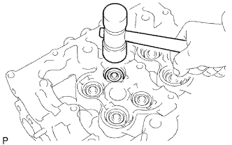
- NOTICE:
- Be careful not to damage the valve stem tip.
| 7. INSTALL VALVE LIFTER |
Install the valve lifter.
Check that the valve lifter rotates smoothly by hand.