INSTALLATION
Removal / installation · Vehicles built Jun 2011 – Jul 2012
Versions by build date: Jun 2011 – Jul 2012 Aug 2012 – Jul 2013 from Aug 2013
- NOTICE:
- When replacing the injectors (including shuffling the injectors between the cylinders), common rail or cylinder head, it is necessary to replace the injection pipes with new ones.
- When replacing the fuel supply pump, common rail, cylinder block, cylinder head, cylinder head gasket or timing gear case, it is necessary to replace the fuel inlet pipe with a new one.
- When replacing the injectors (including shuffling the injectors between the cylinders), common rail or cylinder head, it is necessary to replace the injection pipes with new ones.
| 1. INSTALL TIMING GEAR CASE ASSEMBLY |

Install 2 new O-rings to the cylinder block.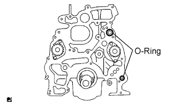

Remove any old seal packing (FIPG material) from the timing gear case and cylinder block.
Set a new gasket to the timing gear case.
Apply seal packing to the areas shown in the illustration.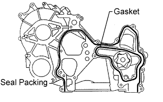
- Seal packing:
- Toyota Genuine Seal Packing Black, Three Bond 1207B or equivalent
- Seal diameter:
- 4 mm (0.15 in.)
- NOTICE:
- After applying seal packing, install the timing gear case within 3 minutes and tighten the bolts within 15 minutes.
- Do not start the engine for at least 2 hours after the installation.
- After applying seal packing, install the timing gear case within 3 minutes and tighten the bolts within 15 minutes.
Align the "2" timing marks of the No. 1 balance shaft driven gear and oil pump drive gear, and install the timing gear case to the cylinder block.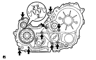
Install the timing gear case with the 8 bolts and union bolt.
- Torque:
- 13 N*m{ 133 kgf*cm , 10 ft.*lbf } for bolt
- 16 N*m{ 163 kgf*cm , 12 ft.*lbf } for union bolt
Make sure that the oil pump drive gear rotates smoothly.
- NOTICE:
- If the gear does not rotate smoothly, remove the 8 bolts and union bolt to release the gear. Then install the bolts and gear again.
| 2. INSTALL OIL STRAINER SUB-ASSEMBLY |
Install a new gasket and the oil strainer with the 2 bolts and nut.
- Torque:
- 8.0 N*m{ 82 kgf*cm , 71 in.*lbf }
| 3. INSTALL OIL PAN SUB-ASSEMBLY |
Remove any old seal packing (FIPG) from the oil pan and cylinder block.
Apply seal packing to the areas shown in the illustration.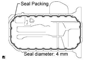
- Seal packing:
- Toyota Genuine Seal Packing Black, Three Bond 1207B or equivalent
- Seal diameter:
- 4 mm (0.15 in.)
- NOTICE:
- After applying seal packing, install the oil pan within 3 minutes and tighten the bolts within 15 minutes.
- Do not start the engine for at least 2 hours after the installation.
- After applying seal packing, install the oil pan within 3 minutes and tighten the bolts within 15 minutes.
Install the oil pan with the 22 bolts and 2 nuts.
- Torque:
- 12 N*m{ 122 kgf*cm , 9 ft.*lbf }
| 4. INSTALL FUEL SUPPLY PUMP ASSEMBLY |
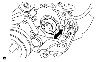 |
Check that the injection gear in the timing gear case moves back and forth smoothly.
Install a new O-ring to the pump.
Apply a light coat of engine oil to the O-ring.
Align the set key on the drive shaft with the groove of the injection gear.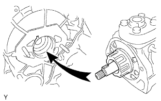
Install the pump with the 2 nuts.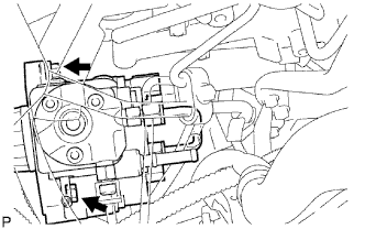
- Torque:
- 21 N*m{ 214 kgf*cm , 15 ft.*lbf }
Set a new O-ring before tightening the set nut.
Using SST, hold the crankshaft pulley and install the set nut.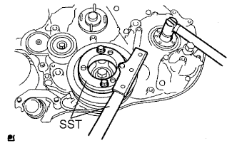
- SST
- 09213-58013
09330-00021
- Torque:
- 64 N*m{ 653 kgf*cm , 47 ft.*lbf }
Move the pump drive shaft pulley back and forth to check the thrust clearance of the injection pump drive shaft.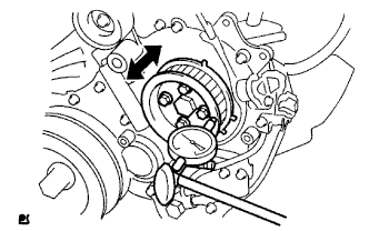
- Thrust clearance:
- 0.15 to 0.55 mm (0.0059 to 0.0217 in.)
Connect the 2 connectors.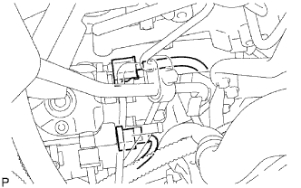
Connect the 2 fuel hoses.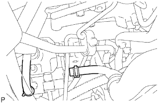
Temporarily install the fuel inlet pipe with the union nuts.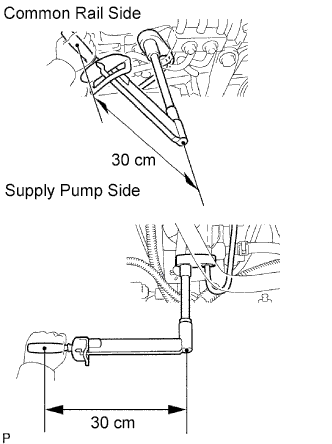
- NOTICE:
- If the supply pump is replaced, the fuel inlet pipe must be replaced.
- Keep the fuel inlet pipe free of foreign matter.
- If the supply pump is replaced, the fuel inlet pipe must be replaced.
Using a 17 mm union nut wrench, tighten the injection pipe union nut on the common rail side.
- Torque:
- 32 N*m{ 326 kgf*cm , 24 ft.*lbf } for use with union nut wrench
- 35 N*m{ 357 kgf*cm , 26 ft.*lbf } for use without union nut wrench
- HINT:
- Use a torque wrench with a fulcrum length of 30 cm (11.81 in.).
Using a 17 mm union nut wrench, tighten the injection pipe union nut on the supply pump side.
- Torque:
- 32 N*m{ 326 kgf*cm , 24 in.*lbf } for use with union nut wrench
- 35 N*m{ 357 kgf*cm , 26 ft.*lbf } for use without union nut wrench
Install the oil level gauge guide with the 2 bolts.
- Torque:
- 8.0 N*m{ 82 kgf*cm , 71 in.*lbf }
Install the clamp with the bolt.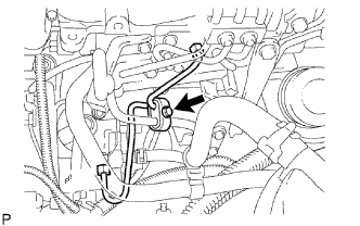
- Torque:
- 5.0 N*m{ 51 kgf*cm , 44 in.*lbf }
| 5. INSTALL INJECTION GEAR |
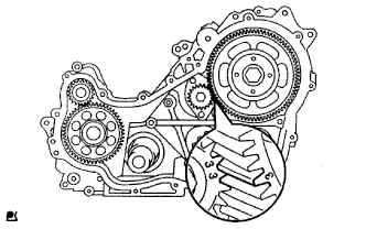 |
Align the "3" timing marks of the injection gear and balance No. 2 shaft driven gear, and install the injection gear.
- NOTICE:
- Fit the key (protrusion) of the supply pump to the key slot of the injection gear.
Set a new O-ring and then temporarily install the nut. Using your hand, check the thrust clearance of the supply pump drive shaft by driving the injection gear.
- Thrust clearance:
- 0.15 to 0.55 mm (0.0059 to 0.0217 in.)
- HINT:
- If the clearance is not within the specified range, remove the injection gear again and reinstall it.
| 6. INSTALL CRANKSHAFT TIMING GEAR |
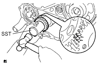 |
Align the "1" timing marks of the oil pump drive gear and crankshaft timing gear as shown in the illustration.
Using SST, install the crankshaft timing gear.
- SST
- 09223-00010
| 7. INSTALL NO. 1 IDLE GEAR |
Install the No. 1 idle gear shaft to the cylinder block.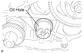
Align the "4" timing marks of the No. 1 idle gear and injection gear, as shown in the illustration.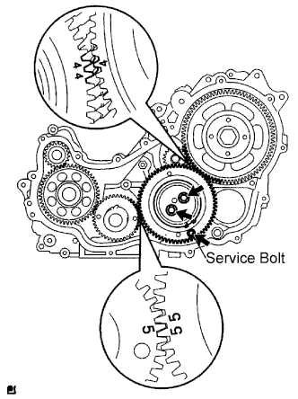
Align the "5" timing marks of the No. 1 idle gear and crankshaft timing gear, and install the No. 1 idle gear, as shown in the illustration.
Install the idle gear thrust plate with the 2 bolts.
- Torque:
- 50 N*m{ 510 kgf*cm , 37 ft.*lbf }
Remove the service bolt.
Install the No. 1 crankshaft sensor plate.
| 8. INSTALL TIMING GEAR COVER |
Install a new O-ring to the timing gear case.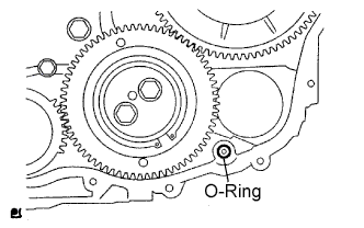
Remove any old seal packing (FIPG material) from the timing gear cover.
Apply seal packing to the areas shown in the illustration.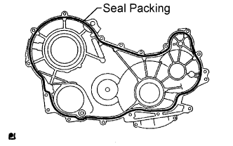
- Seal packing:
- Toyota Genuine Seal Packing Black, Three Bond 1207B or equivalent
- Seal diameter:
- 4 mm (0.15 in.)
- NOTICE:
- After applying seal packing, install the gear cover within 3 minutes and tighten the bolts and nuts within 15 minutes.
- Do not start the engine for at least 2 hours after the installation.
- After applying seal packing, install the gear cover within 3 minutes and tighten the bolts and nuts within 15 minutes.
Install the cover with the 14 bolts and 2 nuts.
- Torque:
- 13 N*m{ 133 kgf*cm , 10 ft.*lbf }
Install the No. 1 vacuum transmitting pipe with the bolt.
- Torque:
- 8.0 N*m{ 82 kgf*cm , 71 in.*lbf }
| 9. INSTALL CRANKSHAFT POSITION SENSOR |
Install the crankshaft position sensor with the bolt.
- Torque:
- 8.5 N*m{ 87 kgf*cm , 75 in.*lbf }
| 10. INSTALL CAMSHAFT POSITION SENSOR |
Install the camshaft position sensor with the bolt.
- Torque:
- 8.5 N*m{ 87 kgf*cm , 75 in.*lbf }
| 11. INSTALL CRANKSHAFT PULLEY |
Align the pulley set key with the key groove of the pulley.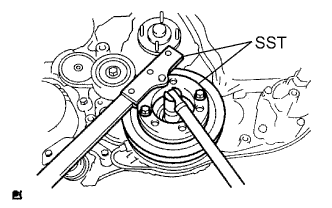
Using SST, install the pulley bolt.
- SST
- 09213-58014
09330-00021
- Torque:
- 365 N*m{ 3722 kgf*cm , 269 ft.*lbf }
| 12. INSTALL PUMP DRIVE SHAFT PULLEY |
Install a new O-ring to the supply pump.
Temporarily install the supply pump with the nut.
Using SST, hold the crankshaft pulley and tighten the nut.
- SST
- 09213-58014
09330-00021
- Torque:
- 64 N*m{ 653 kgf*cm , 47 ft.*lbf }
Install the No. 2 camshaft timing pulley flange and pump drive shaft pulley with the 4 bolts.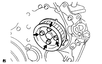
- Torque:
- 31 N*m{ 316 kgf*cm , 23 ft.*lbf }
Using a dial indicator, check the thrust clearance of the pump drive shaft while moving the pump drive shaft pulley back and forth.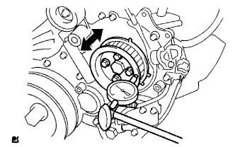
- Thrust clearance:
- 0.15 to 0.55 mm (0.0059 to 0.0217 in.)
- HINT:
- If the clearance is not within the specified range, remove and reinstall the supply pump and pump drive shaft pulley. Then repeat the step above.
| 13. INSTALL VANE PUMP ASSEMBLY |
Install a new O-ring to the vane pump.
Install the vane pump with the 2 nuts.
- Torque:
- 41 N*m{ 418 kgf*cm , 30 ft.*lbf }
| 14. INSTALL VACUUM PUMP ASSEMBLY |
Install 2 new O-rings to the vacuum pump.
Install the vacuum pump with the 2 nuts.
- Torque:
- 21 N*m{ 210 kgf*cm , 15 ft.*lbf }
| 15. INSTALL WATER PUMP ASSEMBLY |
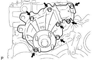 |
Install a new gasket and the water pump with the 5 bolts and 2 nuts.
- Torque:
- 13 N*m{ 133 kgf*cm , 10 ft.*lbf }
| 16. INSTALL NO. 2 TIMING BELT COVER |
Apply seal packing (FIPG) to the specified areas shown in the illustration.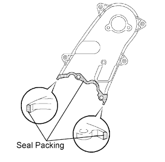
- Seal packing:
- Toyota Genuine Seal Packing Black, Three Bond 1207B or equivalent
- NOTICE:
- After applying FIPG, install the No. 2 timing belt cover within 3 minutes and tighten its bolts and nut within 15 minutes.
Install the No. 2 timing belt cover with the 4 bolts and nut.
- Torque:
- 10 N*m{ 102 kgf*cm , 7 ft.*lbf }
| 17. INSTALL NO. 1 TIMING BELT IDLER SUB-ASSEMBLY |
Install the timing belt idler and a new spacer with the bolt.
- Torque:
- 35 N*m{ 357 kgf*cm , 26 ft.*lbf }
| 18. INSTALL CAMSHAFT TIMING PULLEY |
Install the camshaft timing pulley.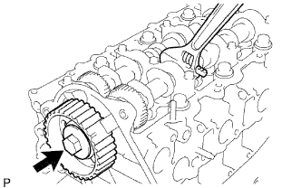
Fasten the bolt of the camshaft timing pulley by holding the camshaft with a wrench.
- Torque:
- 98 N*m{ 1000 kgf*cm , 72 ft.*lbf }
| 19. INSTALL CYLINDER HEAD COVER SUB-ASSEMBLY |
Install 4 new No. 3 cylinder head cover gaskets to the cylinder head cover in the directions shown in the illustration.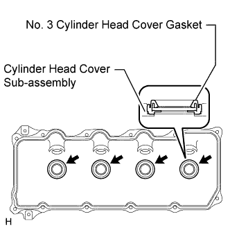
- NOTICE:
- Do not install the No. 3 cylinder head cover gaskets at an angle.
- Check that there is no foreign matter at the installation location of the No. 3 cylinder head cover gaskets.
- Do not install the No. 3 cylinder head cover gaskets at an angle.
Remove any old seal packing (FIPG) material from the cylinder head.
Apply seal packing to the specific areas shown in the illustration.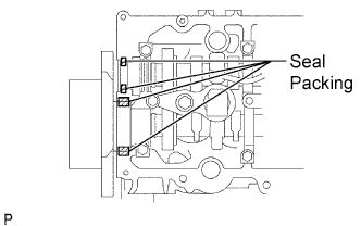
- Seal packing:
- Toyota Genuine Seal Packing Black, Three Bond 1207B or equivalent
- NOTICE:
- Remove any oil from the contact surface.
- Install the head cover within 3 minutes after applying seal packing.
- Do not start the engine for at least 2 hours after installing the seal packing.
- Remove any oil from the contact surface.
Install a new cylinder head cover gasket and the cylinder head cover with the 10 bolts and 2 nuts.
- Torque:
- 9.0 N*m{ 92 kgf*cm , 80 in.*lbf }
Install 4 new nozzle holder seals.
Connect the ventilation hose.
Connect the 4 connectors and install the 3 bolts.
- Torque:
- 13 N*m{ 127 kgf*cm , 9 ft.*lbf }
| 20. INSTALL NO. 4 INJECTION PIPE SUB-ASSEMBLY |
- NOTICE:
- When replacing an injector, it is necessary to replace the 4 injection pipes with new ones.
- Keep the joints of the injection pipe clean.
- When replacing an injector, it is necessary to replace the 4 injection pipes with new ones.
Temporarily install the No. 4 injection pipe with the union nuts.
Install the 2 bolts.
- Torque:
- 13 N*m{ 130 kgf*cm , 9 ft.*lbf }
- NOTICE:
- If an injection pipe clamp is removed from the No. 4 injection pipe, replace the injection clamp with a new one.
- Make sure that the inner-rubbers of the injection pipe fit inside the clamps.
- When installing the pipe, check that the inner-rubbers and the clamps are in their proper positions.
- If an injection pipe clamp is removed from the No. 4 injection pipe, replace the injection clamp with a new one.
Using a 17 mm union nut wrench, tighten the injection pipe union nut on the common rail side.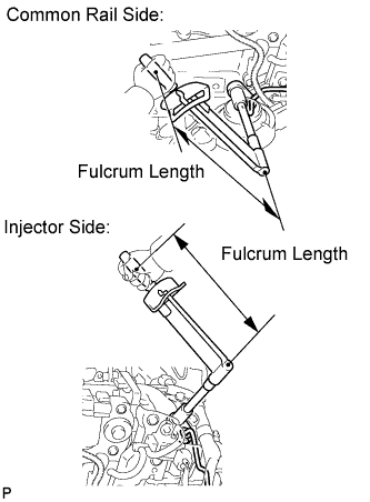
- Torque:
- 35 N*m{ 357 kgf*cm , 26 ft.*lbf }
- NOTICE:
- Use the formula to calculate special torque values for situations where a union nut wrench is combined with a torque wrench (Click here).
Using a 17 mm union nut wrench, tighten the injection pipe union nuts on the injector side.
- Torque:
- 35 N*m{ 357 kgf*cm , 26 ft.*lbf }
- NOTICE:
- Use the formula to calculate special torque values for situations where a union nut wrench is combined with a torque wrench (Click here).
| 21. INSTALL NO. 1, NO. 2 AND NO. 3 INJECTION PIPE SUB-ASSEMBLY |
- NOTICE:
- When replacing an injector, it is necessary to replace the 4 injection pipes with new ones.
- Keep the joints of the injection pipe clean.
- When replacing an injector, it is necessary to replace the 4 injection pipes with new ones.
Temporarily install the No. 1, No. 2 and No. 3 injection pipes with the union nuts.
Install the No. 2 and No. 3 injection pipe clamps with the bolt and 2 nuts, as shown in the illustration.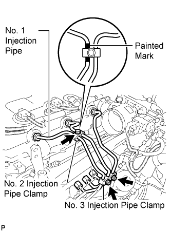
- Torque:
- 5.0 N*m{ 51 kgf*cm , 44 in.*lbf }
- HINT:
- If the painted mark on the No. 1 injection pipe has disappeared, use the illustration as a reference to install the clamps.
Using a 17 mm union nut wrench, tighten the injection pipe union nuts on the common rail side.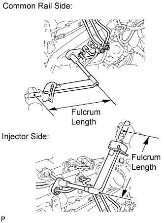
- Torque:
- 35 N*m{ 357 kgf*cm , 26 ft.*lbf }
- NOTICE:
- Use the formula to calculate special torque values for situations where a union nut wrench is combined with a torque wrench (Click here).
Using a 17 mm union nut wrench, tighten the injection pipe union nuts on the injector side.
- Torque:
- 35 N*m{ 357 kgf*cm , 26 ft.*lbf }
- NOTICE:
- Use the formula to calculate special torque values for situations where a union nut wrench is combined with a torque wrench (Click here).
| 22. INSTALL FUEL INLET PIPE SUB-ASSEMBLY |
Temporarily install the fuel inlet pipe with the union nuts.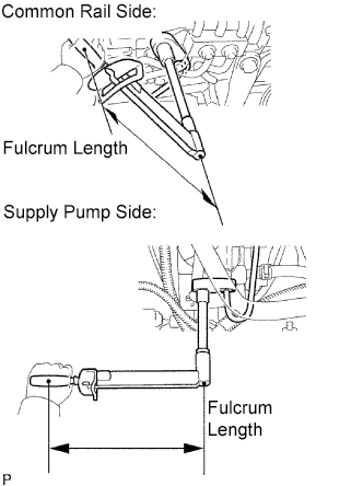
- NOTICE:
- When replacing the common rail, it is necessary to replace the 4 injection pipes and fuel inlet pipe with new ones.
- Be careful that dust, dirt or any other foreign matter does not contact the joint area of the fuel inlet pipe.
- When replacing the common rail, it is necessary to replace the 4 injection pipes and fuel inlet pipe with new ones.
Using a 17 mm union nut wrench, tighten the fuel inlet pipe union nut on the common rail side.
- Torque:
- 35 N*m{ 357 kgf*cm , 26 ft.*lbf }
- NOTICE:
- Use the formula to calculate special torque values for situations where a union nut wrench is combined with a torque wrench (Click here).
Using a 17 mm union nut wrench, tighten the fuel inlet pipe union nut on the supply pump side.
- Torque:
- 35 N*m{ 357 kgf*cm , 26 ft.*lbf }
- NOTICE:
- Use the formula to calculate special torque values for situations where a union nut wrench is combined with a torque wrench (Click here).
Install a new O-ring to the engine oil level dipstick guide.
Install the engine oil level dipstick guide with the bolt.
- Torque:
- 8.0 N*m{ 82 kgf*cm , 71 in.*lbf }
Install the clamp with the bolt.
- Torque:
- 5.0 N*m{ 51 kgf*cm , 44 in.*lbf }
Install the engine oil level dipstick.
| 23. INSTALL MANIFOLD STAY |
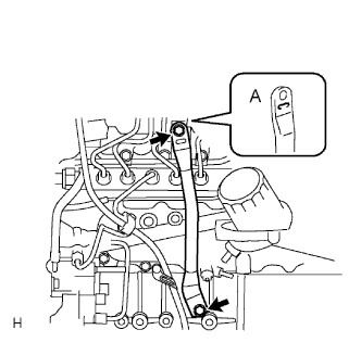 |
Install the stay with the 2 bolts.
- Torque:
- 19 N*m{ 194 kgf*cm , 14 ft.*lbf }
- HINT:
- The stay's indented area (labeled A) must face the manifold.
| 24. INSTALL NO. 1 COMPRESSOR MOUNTING BRACKET |
Install the No. 1 compressor mounting bracket with the 4 bolts.
- Torque:
- 45 N*m{ 459 kgf*cm , 33 ft.*lbf }
| 25. INSTALL V-RIBBED BELT TENSIONER ASSEMBLY |
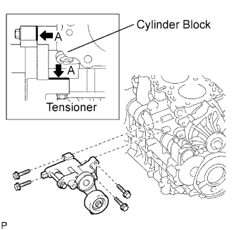 |
Install the tensioner with the 4 bolts.
- Torque:
- 21 N*m{ 214 kgf*cm , 15 ft.*lbf }
- HINT:
- Firmly press and hold the tensioner against the cylinder block to eliminate any gaps in the areas labeled A in the illustration. Then uniformly tighten the 4 bolts.
| 26. INSTALL GENERATOR BRACKET |
Install the generator bracket with the bolt.
- Torque:
- 25 N*m{ 255 kgf*cm , 18 ft.*lbf }
| 27. INSTALL GENERATOR ASSEMBLY |
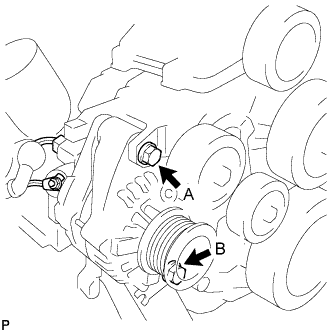 |
Install the generator with the 2 bolts.
- Torque:
- 62 N*m{ 632 kgf*cm , 46 ft.*lbf } for bolt A
- 25 N*m{ 255 kgf*cm , 18 ft.*lbf } for bolt B
Install the generator wire with the nut.
- Torque:
- 9.8 N*m{ 100 kgf*cm , 87 in.*lbf }
Connect the generator connector.
| 28. INSTALL NO. 2 IDLE PULLEY ASSEMBLY |
| 29. INSTALL TIMING BELT |
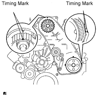 |
Check that the timing marks are aligned as shown in the illustration.
- HINT:
- If reusing the timing belt, align the points marked during removal, and install the belt with the arrow pointing in the direction of engine revolution.
- NOTICE:
- The engine should be cold.
- When turning the crankshaft, the valve heads will hit against the piston's top position. Do not turn it more than necessary.
- The engine should be cold.
Using a 10 mm hexagon wrench, install the and timing belt idler pulley and new washer with the bolt.
- Torque:
- 35 N*m{ 357 kgf*cm , 26 ft.*lbf }
Check that the idler pulley moves smoothly.
If it does not move smoothly, check the idler sub-assembly and washer.
Install the timing belt to the pump drive shaft pulley, camshaft timing pulley and No. 1 timing belt idler in sequence.
Place the tensioner upright. Then set the press to the top of the tensioner.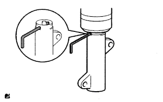
- NOTICE:
- Do not scratch or deform the rod end.
- Press in the tensioner rod upward.
- Protect the tip of the push rod with a cloth in order to prevent damage.
- Do not scratch or deform the rod end.
Using a press, slowly push in the push rod using 981 to 9800 N (100 to 999 kgf, 220 to 2203 lbf) of force.
- NOTICE:
- Do not impose a load of over 9800 N (999 kgf, 2203 lbf) to the push rod.
Align the holes of the push rod and housing. Then pass a 1.27 mm hexagon wrench through the holes to keep the setting position of the push rod.
Install the timing belt tensioner with the 2 bolts while pushing the idler pulley toward the timing belt.
Tighten the 2 bolts.
- Torque:
- 13 N*m{ 133 kgf*cm , 10 ft.*lbf }
- NOTICE:
- Uniformly tighten the 2 bolts and install the tensioner.
Remove the 1.5 mm hexagon wrench from the tensioner.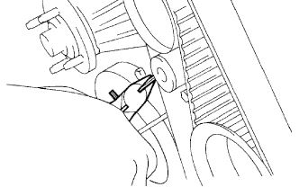
Turn the crankshaft clockwise 720° and check that the timing marks are aligned as shown in the illustration.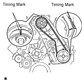
| 30. INSTALL NO. 1 TIMING BELT TENSIONER ASSEMBLY |
| 31. INSTALL NO. 1 TIMING BELT COVER |
Install the timing belt cover with the 6 bolts.
- Torque:
- 6.0 N*m{ 61 kgf*cm , 53 in.*lbf }
Install the wire harness clamp.
Install the water hose clamp with the bolt.
- Torque:
- 18 N*m{ 184 kgf*cm , 13 ft.*lbf }
| 32. INSTALL ENGINE ASSEMBLY |