REASSEMBLY
Removal / installation · Vehicles built from Jun 2011
- HINT:
- Use high temperature-resistant grease to lubricate the bearings and sliding parts when assembling the starter.
| 1. INSTALL PLANETARY CARRIER SHAFT SUB-ASSEMBLY |

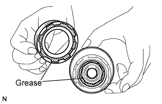  |
Apply high-temperature grease to the part of the internal gear that contacts the shock absorber and planetary gears, and the part of the shock absorber that contacts the internal gear.
Align the hollow of the internal gear with the protrusion inside the shock absorber.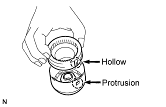
Inset and turn the internal gear so that it interlocks with the shock absorber.
Apply high-temperature grease to the plate washer, and install it to the planetary shaft.
Install the planetary shaft to the internal gear with shock absorber.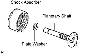
Apply high-temperature grease to the center bearing.
Install the center bearing.
Using snap ring pliers, install the plate washer and snap ring.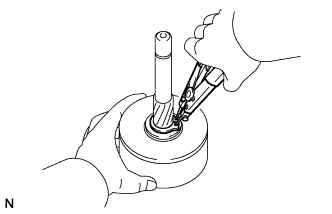
| 2. INSTALL STARTER CLUTCH SUB-ASSEMBLY |
Apply high-temperature grease to the spline of the starter clutch and the stop collar.
Place the starter clutch and stop collar on the planetary shaft.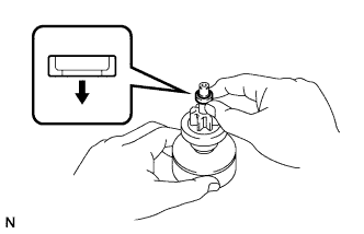
Apply high-temperature grease to the snap ring, and install it to the planetary shaft groove.
Using a vise, compress the snap ring between aluminum plates.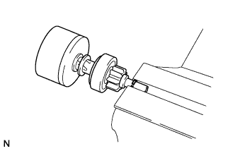
Holding the starter clutch, tap the planetary shaft with a plastic-faced hammer to install the stop collar onto the snap ring.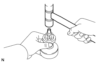
| 3. INSTALL PLANETARY GEAR |
Apply high-temperature grease to the planetary gears and flange pins of the planetary shaft.
Install the plate washer and 3 planetary gears.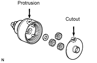
Align the cutout of the plate with the protrusion inside the shock absorber, and install the plate.
| 4. INSTALL DRIVE LEVER AND STARTER CLUTCH WITH SHOCK ABSORBER |
Apply high-temperature grease to the bearing of the starter drive housing.
Apply high-temperature grease to the starter drive lever as shown in the illustration.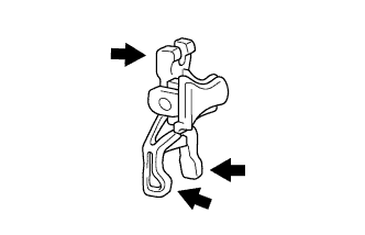
Install the starter drive lever to the starter clutch sub-assembly.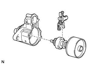
Align the protrusion of the shock absorber with the cutout of the starter drive housing and install the drive lever and starter clutch with shock absorber.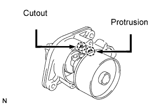
| 5. INSTALL STARTER BRUSH HOLDER ASSEMBLY |
Install the starter armature to the starter yoke.
Install 2 new O-rings to the starter yoke.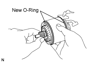
Install the brush holder to the armature.
Install the 4 starter brushes to the starter brush holder.
Using a screwdriver, pull back the spring.
Install the brush to the brush holder.
- NOTICE:
- Check that positive (+) lead wires are not grounded.
| 6. INSTALL STARTER COMMUTATOR END FRAME ASSEMBLY |
Apply high-temperature grease to the bearing of the end frame.
Install the end frame with the 2 screws.
- Torque:
- 1.5 N*m{ 15 kgf*cm , 13 in.*lbf }
| 7. INSTALL STARTER YOKE ASSEMBLY |
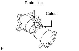 |
Align the cutout of the starter yoke with the protrusion of the shock absorber.
Install the starter yoke with armature with the 2 through bolts.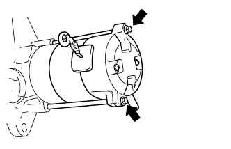
- Torque:
- 5.9 N*m{ 60 kgf*cm , 52 in.*lbf }
| 8. INSTALL MAGNET STARTER SWITCH ASSEMBLY |
Install the plunger cover to the magnet starter switch assembly.
Attach the plunger of the magnet starter switch assembly to the drive lever from the upper side.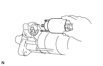
Install the magnet starter switch assembly with the 2 nuts.
- Torque:
- 8.3 N*m{ 85 kgf*cm , 73 in.*lbf }
Connect the lead wire to the terminal, and install the nut.
- Torque:
- 9.8 N*m{ 100 kgf*cm , 87 in.*lbf }