TERMINALS OF ECU
System information · Vehicles built from Jun 2011
| CHECK AIR CONDITIONING AMPLIFIER ASSEMBLY (w/ HOT GAS HEATER) |
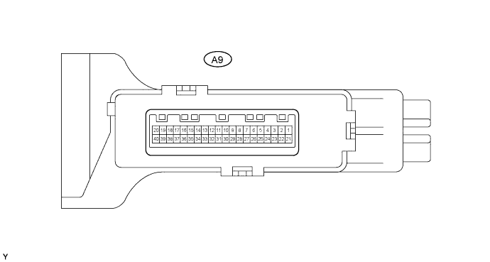

Disconnect the A9 air conditioning amplifier connector.
Measure the voltage and resistance of the wire harness side connector.
Symbols (Terminal No.)
Wiring Color
Terminal Description
Condition
Specified Condition
+B (A9-40) - GND (A9-29)
L-Y - L
For memory backup
Always
10 to 14 V
IG+ (A9-20) - GND (A9-29)
R-L - L
Power source (IG)
Ignition switch OFF
Below 1 V
IG+ (A9-20) - GND (A9-29)
R-L - L
Power source (IG)
Ignition switch ON
10 to 14 V
GND (A9-29) - Body ground
L - Body ground
Ground
Always
Below 1 Ω
ACON (A9-8) - GND (A9-29)
R-G - L
A/C switch signal
A/C switch OFF
Below 1 V
ACON (A9-8) - GND (A9-29)
R-G - L
A/C switch signal
Ignition switch START
Blower switch ON
A/C switch ON
10 to 14 V
IND- (A9-9) - GND (A9-29)
R-L - L
A/C indicator light signal
A/C switch OFF
Below 1 V
IND- (A9-9) - GND (A9-29)
R-L - L
A/C indicator light signal
Ignition switch START
Blower switch ON
A/C switch ON
10 to 14 V
BLW (A9-38) - GND (A9-29)
R-L - L
Max HOT switch signal
Temperature control knob: Max HOT
Below 1 Ω
BLW (A9-38) - GND (A9-29)
R-L - L
Max HOT switch signal
Temperature control knob: Max HOT
10k Ω or higher
HEAT (A9-5) - GND (A9-29)
L-O - L
Heater switch signal
Heater switch ON
Below 1 Ω
HEAT (A9-5) - GND (A9-29)
L-O - L
Heater switch signal
Heater switch OFF
10k Ω or higher
MGC (A9-19) - GND (A9-29)
B - L
Magnet clutch relay signal
Ignition switch START
Blower switch ON
10 to 14 V
MGC (A9-19) - GND (A9-29)
B - L
Magnet clutch relay signal
Ignition switch START
Blower switch OFF
Below 1 V
TAIL (A9-7) - GND (A9-29)
G - L
Light control switch signal
Light control switch ON
10 to 14 V
TAIL (A9-7) - GND (A9-29)
G - L
Light control switch signal
Light control switch OFF
Below 1 V
- If the result is not as specified, there may be a malfunction on the wire harness side.
- If the result is not as specified, there may be a malfunction on the wire harness side.
Reconnect the A9 connector.
Measure the voltage and resistance of the connector.
Symbols (Terminal NO.)
Wiring Color
Terminal Description
Condition
Specified Condition
S5 (A9-13) - SG-3 (A9-12)
R-B - BR-Y
Power supply for pressure sensor
Ignition switch ON
4.5 to 5.5 V
PRE (A9-4) - SG-3 (A9-12)
BR - BR-Y
Air conditioner pressure switch signal
Ignition switch START
Refrigerant pressure normal: 0.18 MPa (1.9 kgf/cm2, 26 psi) to 3.03 MPa (31.0 kgf/cm2, 440 psi)
Blower switch ON
A/C switch ON
0.74 to 4.66 V
PRE (A9-4) - SG-3 (A9-12)
BR - BR-Y
Air conditioner pressure switch signal
Ignition switch START
Blower switch ON
A/C switch ON
Refrigerant pressure abnormal: pressure less than 0.18 MPa (1.9 kgf/cm2, 26 psi)
Below 0.74 V
PRE (A9-4) - SG-3 (A9-12)
BR - BR-Y
Air conditioner pressure switch signal
Ignition switch START
Blower switch ON
A/C switch ON
Refrigerant pressure abnormal: pressure more than 3.03 MPa (31.0 kgf/cm2, 440 psi)
Above 4.66 V
TAM (A9-25) - SG-3 (A9-12)
W-G - BR-Y
Ambient temperature sensor signal
Ignition switch ON
Ambient temperature is 25 °C (77°F)
1.35 to 1.75 V
SG-3 (A9-12) - Body ground
BR-Y - Body ground
Ground for Ambient temperature sensor and pressure sensor
Always
Below 1 Ω
MGC (A9-19) - GND (A9-29)
B - L
Magnet clutch signal
Ignition switch START
Magnet clutch is engaged
10 to 14 V
MGC (A9-19) - GND (A9-29)
B - L
Magnet clutch signal
Ignition switch START
Magnet clutch is not engaged
Below 1 V
TE (A9-24) - SG-1 (A9-31)
G - P
Evaporator temperature sensor signal
Ignition switch ON
Evaporator temperature is 0°C (32°F)
2.0 to 2.4 V
TE (A9-24) - SG-1 (A9-31)
G - P
Evaporator temperature sensor signal
Ignition switch ON
Evaporator temperature is 15 °C (59°F)
1.4 to 1.8 V
SG-1 (A9-31) - Body ground
P - Body ground
Ground for evaporator temperature sensor
Always
Below 1 Ω
ACT (A9-39) - GND (A9-29)
R-L - L
Magnet on permit signal
Ignition switch START
Blower switch OFF
A/C switch OFF
Below 1 V
ACT (A9-39) - GND (A9-29)
R-L - L
Magnet on permit signal
Ignition switch START
Blower switch ON
A/C switch ON
10 to 14 V
AC1 (A9-39) - GND (A9-29)
Y - L
Idle-up request signal
Ignition switch START
Magnet clutch is not engaged
Below 1 V
AC1 (A9-39) - GND (A9-29)
Y - L
Idle-up request signal
Ignition switch START
Magnet clutch is engaged
10 to 14 V
BLW (A9-38) - GND (A9-29)
R-1 - L
Max HOT switch signal
Ignition switch ON
Temperature control knob: Max HOT
10 to 14 V
BLW (A9-38) - GND (A9-29)
R-1 - L
Max HOT switch signal
Ignition switch ON
Temperature control knob: except Max HOT
Below 1 V
HEAT (A9-5) - GND (A9-29)
L-O - L
Heater switch input signal
Ignition switch START
Heater switch ON
Temperature control knob: Max HOT
Blower switch ON
Coolant temperature 65 °C (149°F) or lower
Below 1 V
HEAT (A9-5) - GND (A9-29)
L-O - L
Heater switch input signal
Ignition switch START
Temperature control knob: except Max HOT
Heater switch OFF
Blower switch ON
Coolant temperature 65 °C (149°F) or lower
10 to 14 V
SWIN (A9-15) - GND (A9-29)
P - L
Heater switch indicator light signal
Ignition switch START
Temperature control knob: Max HOT
Heater switch ON
Blower switch ON
Coolant temperature 65 °C (149°F) or lower
Below 1 V
SWIN (A9-15) - GND (A9-29)
P - L
Heater switch indicator light signal
Ignition switch START
Temperature control knob: except Max HOT
Heater switch OFF
Blower switch ON
Coolant temperature 65 °C (149°F) or lower
10 to 14 V
MGV (A9-17) - GND (A9-29)
Y-B - L
Magnetic valve operating signal
Ignition switch ON
10 to 14 V
MGV (A9-17) - GND (A9-29)
G - L
Magnetic valve operating signal
Ignition switch START
Temperature Control knob: Max HOT
A/C switch ON
Blower switch ON
Heater switch ON
Coolant temperature 65 °C (149°F) or lower
Below 1 V
ALT (A9-37) - GND (A9-29)
G - L
Generator
Engine running
Pulse generation
PTCR (A9-26) - GND (A9-29)
L-W - L
Heater switch output signal
Ignition switch START
Temperature Control knob: Max HOT
Heater switch ON
Coolant temperature 65 °C (149°F) or lower
Blower switch ON
10 to 14 V
PTCR (A9-26) - GND (A9-29)
L-W - L
Heater switch output signal
Ignition switch START
Temperature Control knob: Max HOT
Heater switch OFF
Coolant temperature 65 °C (149°F) or lower
Blower switch ON
Below 1 V
TW (A9-32) - GND (A9-29)
P - L
Water temperature signal
Ignition switch ON
Pulse generation
TACO (A9-33) - GND (A9-29)
B-W - L
Tachometer signal
Engine running
Pulse generation
(see waveform 1)
PTC1 (A9-3) - GND (A9-29)
R-W - L
PTC heater relay signal
Ignition switch START
Heater switch ON
Temperature Control knob: Max HOT
Coolant temperature 65 °C (149°F) or lower
Blower switch ON
Below 1 V
PTC1 (A9-3) - GND (A9-29)
GR - L
PTC heater relay signal
Ignition switch START
Heater switch OFF
Temperature Control knob: Max HOT
Coolant temperature 65 °C (149°F) or lower
Blower switch ON
10 to 14 V
PTC2 (A9-2) - GND (A9-29)
GR - L
PTC heater relay signal
Ignition switch START
Heater switch ON
Temperature Control knob: Max HOT
Coolant temperature 65 °C (149°F) or lower
Blower switch ON
Below 1 V
PTC2 (A9-2) - GND (A9-29)
GR - L
PTC heater relay signal
Ignition switch START
Heater switch OFF
Temperature Control knob: Max HOT
Coolant temperature 65 °C (149°F) or lower
Blower switch ON
10 to 14 V
- If the result is not as specified, the air conditioning amplifier may have a malfunction.
- If the result is not as specified, the air conditioning amplifier may have a malfunction.
Inspect using an oscilloscope.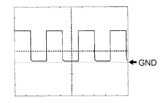
Waveform 1 (Reference)
Item
Content
Symbols (Terminal No.)
TACO (A9-33) - GND (A9-29)
Tool Setting
5 V/DIV., 20 msec./DIV.
Condition
Engine idling
- HINT:
- As engine speed increases, the wavelength shortens.
| CHECK HEATER AMPLIFIER ASSEMBLY (w/ Viscous Heater) |
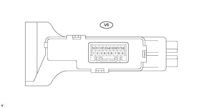
Disconnect the V6 viscous heater amplifier connector.
Measure the voltage and resistance of the wire harness side connector.
Symbols (Terminal NO.)
Wiring Color
Terminal Description
Condition
Specified Condition
+B (V6-9) - GND (V6-15)
L-Y - L
Viscous heater MGC power supply
Always
10 to 14 V
IG (V6-1) - GND (V6-15)
R-L- L
Power source (IG)
Ignition switch OFF
Below 1 V
IG (V6-1) - GND (V6-15)
R-L- L
Power source (IG)
Ignition switch ON
10 to 14 V
GND (V6-15) - Body ground
L - Body ground
Ground
Always
Below 1 Ω
BLW (V6-2) - GND (V6-15)
R-L - L
Max HOT switch signal
Temperature control knob: Max HOT
Below 1 Ω
BLW (V6-2) - GND (V6-15)
R-L - L
Max HOT switch signal
Temperature control knob: except Max HOT
10k Ω or higher
HLS (V6-10) - GND (V6-15)
G - L
Light control switch signal
Light control switch ON
10 to 14 V
HLS (V6-10) - GND (V6-15)
G - L
Light control switch signal
Light control switch OFF
Below 1 Ω
- If the result is not as specified, there may be a malfunction on the wire harness side.
- If the result is not as specified, there may be a malfunction on the wire harness side.
Reconnect the V6 viscous heater amplifier connector.
Measure the voltage and resistance of the wire harness side connector
Symbols (Terminal NO.)
Wiring Color
Terminal Description
Condition
Specified Condition
MGCA (V6-18) - GND (V6-15)
B -L
Magnet clutch signal
Ignition switch START
Magnet clutch is engaged
Below 1 V
MGCA (V6-18) - GND (V6-15)
B -L
Magnet clutch signal
Ignition switch START
Magnet clutch is not engaged
10 to 14 V
ACT (V6-12) - GND (V6-15)
R-L - L*1
V - L*2
Viscous heater permit signal
Ignition switch START
Heater switch ON
Temperature control knob: Max HOT
Blower switch ON
Coolant temperature 65 °C (149°F) or more
Below 1 V
ACT (V6-12) - GND (V6-15)
R-L - L*1
V - L*2
Viscous heater permit signal
Ignition switch START
Heater switch OFF
Temperature control knob: except Max HOT
Blower switch OFF
Coolant temperature 65 °C (149°F) or more
10 to 14 V
AC2 (V6-5) - GND (V6-15)
BR - L
Viscous heater ON signal
Ignition switch START
Heater switch ON
Temperature control knob: Max HOT
Blower switch ON
Coolant temperature 65 °C (149°F) or more
Above 7.8 V
AC2 (V6-5) - GND (V6-15)
BR - L
Viscous heater ON signal
Ignition switch START
Heater switch OFF
Temperature control knob: except Max HOT
Blower switch ON
Coolant temperature 65 °C (149°F) or more
Below 1 V
BLW (V6-2) - GND (V6-15)
R-L - L
Max HOT switch signal
Ignition switch ON
Temperature control knob: Max HOT
Blower switch ON
10 to 14 V
BLW (V6-2) - GND (V6-15)
R-L - L
Max HOT switch signal
Ignition switch ON
Temperature control knob: except Max HOT
Blower switch ON
Below 1 V
SWVC (V6-13) - GND (V6-15)
L-O - L
Heater switch input signal
Ignition switch START
Heater switch ON
Temperature control knob: Max HOT
Blower switch ON
Coolant temperature 65 °C (149°F) or more
Below 1 V
SWVC (V6-13) - GND (V6-15)
L-O - L
Heater switch input signal
Ignition switch START
Heater switch OFF
Temperature control knob: except Max HOT
Blower switch ON
Coolant temperature 65 °C (149°F) or more
10 to 14 V
SWIN (V6-8) - ND (V6-15)
P - L
Heater switch indicator light signal
Ignition switch START
Heater switch ON
Temperature control knob: Max HOT
Blower switch ON
Coolant temperature 65 °C (149°F) or more
10 to 14 V
SWIN (V6-8) - GND
P - L
Heater switch indicator light signal
Ignition switch START
Heater switch OFF
Temperature control knob: except Max HOT
Blower switch ON
Coolant temperature 65 °C (149°F) or more
Below 1 V
TW (V6-4) - GND (V6-15)
P - L
Water temperature signal
Ignition switch START
Pulse generation
TACO (V6-11) - GND (V6-15)
B-W - L
Tachometer signal
Engine running
Pulse generation
(see waveform 1)
ALT (V6-14) - GND (V6-15)
G - L
Generator
Engine running
Pulse generation
PCT1 (V6-6) - GND (V6-15)
R-W - L
PTC heater relay signal
Ignition switch START
Heater switch ON
Temperature control knob: Max HOT
Blower switch ON
Coolant temperature: 65°C (149°F) or lower
10 to 14 V
PTC1 (V6-6) - GND (V6-15)
R-W - L
PTC heater relay signal
Ignition switch START
Heater switch OFF
Temperature control knob: except Max HOT
Blower switch OFF
Coolant temperature: 65°C (149°F) or lower
Below 1 V
PTC2 (V6-7) GND (V6-15)
GR - L
PTC heater relay signal
Ignition switch START
Heater switch ON
Temperature control knob: Max HOT
Blower switch ON
Coolant temperature: 65°C (149°F) or lower
10 to 14 V
PTC2 (V6-7) - GND (V6-15)
GR - L
PTC heater relay signal
Ignition switch START
Heater switch OFF
Temperature control knob: except Max HOT
Blower switch OFF
Coolant temperature: 65°C (149°F) or lower
Below 1 V
- *1: LHD
- *2: RHD
- *1: LHD
Inspect using an oscilloscope.
Waveform 1 (Reference)
Item
Content
Symbols (Terminal No.)
TACO (V6-11) - GND (V6-15)
Tool Setting
5 V/DIV., 20 msec./DIV.
Condition
Engine idling
- HINT:
- As engine speed increases, the wavelength shortens.
| CHECK ECM |
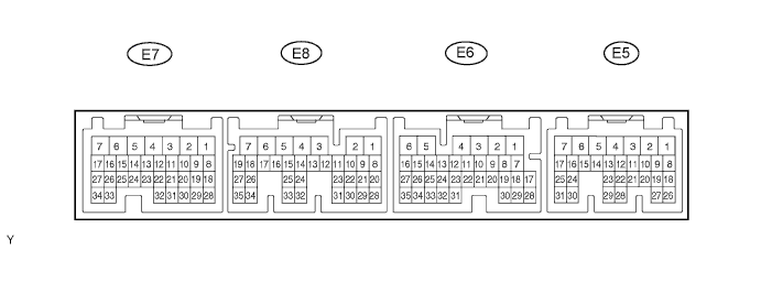
Measure the voltage of the connectors.
2KD-FTV
w/ Hot gas heater Symbols (Terminal NO.)
Wiring color
Terminal Description
Condition
Specified Condition
ACT (E6-19) - E01 (E8-7)
R-L - W-B
Magnet on permit signal
Ignition switch START
Heater switch OFF
Blower switch ON
A/C switch OFF
Below 1 V
ACT (E6-19) - E01 (E8-7)
R-L - W-B
Magnet on permit signal
Ignition switch START
Heater switch ON
Blower switch ON
A/C switch ON
10 to 14 V
AC1 (E6-18) - E01 (E8-7)
Y - W-B
Idle-up request signal
Ignition switch START
Magnet clutch is engaged
Below 1 V
AC1 (E6-18) - E01 (E8-7)
Y - W-B
Idle-up request signal
Ignition switch START
Magnet clutch is not engaged
10 to 14 V
HSW (E6-20) - E01 (E8-7)
L-W - W-B
Heater switch output signal for idle-up
Ignition switch START
Blower switch ON
Power heater switch ON
Temperature control knob: Max HOT
Below 1 V
HSW (E6-20) - E01 (E8-7)
L-W - W-B
Heater switch output signal for idle-up
Ignition switch START
Blower switch OFF
Power heater switch OFF
Temperature control knob: Max HOT
10 to 14 V
THWO (E5-2) - E01 (E8-7)
P -W-B
Ignition switch ON
Ignition switch START
Pulse generation
TACH (E5-4) - E01 (E8-7)
B-W - W-B
Tachometer signal
Engine running
Pulse generation (see waveform 1)
w/ Viscous heater Symbols (Terminal NO.)
Wiring color
Terminal Description
Condition
Specified Condition
ACT (E6-19) - E01 (E8-7)
R-L - W-B*1
V - W-B*2
Viscous heater permit signal
Ignition switch START
Heater switch OFF
Blower switch ON
Coolant temperature: 65°C (149°F) or lower
Temperature control knob: except Max HOT
Below 1 V
ACT (E6-19) - E01 (E8-7)
R-L - W-B*1
V - W-B*2
Viscous heater permit signal
Ignition switch START
Heater switch ON
Blower switch ON
Coolant temperature: 65°C (149°F) or lower
Temperature control knob: Max HOT
10 to 14 V
AC1 (E6-18) - E01 (E8-7)
BR - W-B
Viscous heater on signal
Ignition switch START
Viscous magnet clutch is engaged
Below 1 V
AC1 (E6-18) - E01 (E8-7)
BR - W-B
Viscous heater on signal
Ignition switch START
Viscous magnet clutch is not engaged
10 to 14 V
THWO (E5-2) - E01 (E8-7)
P -W-B
Ignition switch ON
Ignition switch START
Pulse generation
TACH (E5-4) - E01 (E8-7)
B-W - W-B
Tachometer signal
Engine running
Pulse generation (see waveform 1)
- HINT:
- *1: LHD
- *2: RHD
- If the result is not as specified, the ECM may have a malfunction.
Inspect using an oscilloscope.
Waveform 1 (Reference)
Item
Content
Symbols (Terminal No.)
TACH (E5-4) - E01 (E8-7)
Tool Setting
5 V/DIV., 20 msec./DIV.
Condition
Engine idling
- HINT:
- As engine speed increases, the wavelength shortens.