2014 Hilux · Service Manual ENGINE

REMOVAL

Removal / installation · Vehicles built from Aug 2013

Versions by build date: Jun 2011 – Jul 2012 Aug 2012 – Jul 2013 from Aug 2013

NOTICE:
  1. When replacing the injectors (including shuffling the injectors between the cylinders), common rail or cylinder head, it is necessary to replace the injection pipes with new ones.
  2. When replacing the fuel supply pump, common rail, cylinder block, cylinder head, cylinder head gasket or timing gear case, it is necessary to replace the fuel inlet pipe with a new one.
  3. After removing the injection pipes, clean them with a brush and compressed air.


1. REMOVE NO. 1 ENGINE UNDER COVER

2. DRAIN ENGINE COOLANT

CAUTION:
Do not remove the radiator reservoir cap while the engine and radiator are still hot. Pressurized, hot engine coolant and steam may be released and cause serious burns.

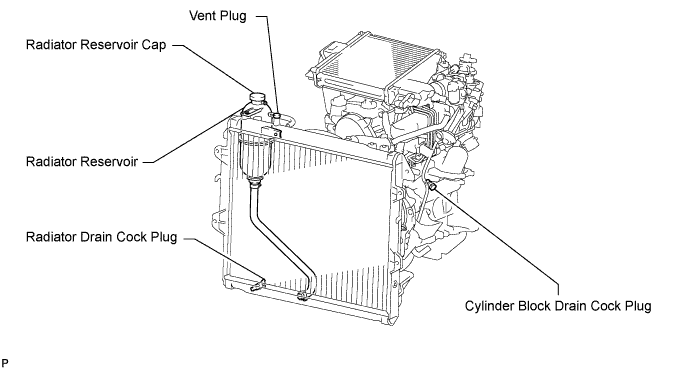
  1. Loosen the radiator drain cock plug.

    HINT:
    Collect the coolant in a container and dispose of it according to the regulations in your area.

  1. A099591E01
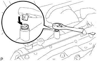
    Drain the coolant by removing the reservoir cap and, using a wrench, remove the vent plug.

  1. Loosen the cylinder block drain cock plug.

    A147246E01


3. DRAIN ENGINE OIL
  1. Remove the oil filler cap.

  1. Remove the oil pan drain plug and gasket, and then drain the engine oil into a container.

  1. Wipe the oil pan and drain plug.

  1. Install a new gasket and the oil pan drain plug.

    Torque:
    34 N*m{ 347 kgf*cm , 25 ft.*lbf }


4. REMOVE FUEL SUPPLY PUMP ASSEMBLY
(Click here)

5. REMOVE COMMON RAIL ASSEMBLY
(Click here)

6. REMOVE STARTER ASSEMBLY
  1. for 2.2 kW Type Bosch Made: (Click here)
  2. for 2.2 kW Type Denso Made: (Click here)
  3. for 2.7 kW Type: (Click here)

7. REMOVE OIL FILTER SUB-ASSEMBLY

  1. A227248E01
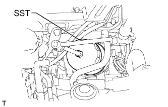
    Using SST, remove the oil filter.
    SST
    09228-07501  

    HINT:
    Insert the drain hose in the oil filter. Put the disposal container beneath the drain hose to collect the oil from the oil filter.


8. REMOVE OIL COOLER COVER SUB-ASSEMBLY
  1. Disconnect the oil pressure switch connector.

  1. Remove the 2 nuts and disconnect the No. 2 vacuum transmitting pipe from the oil cooler cover.

  1. A038741E01
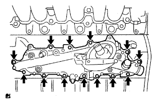
    Remove the 13 bolts, oil cooler cover and gasket.


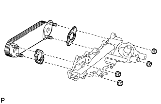
9. REMOVE OIL COOLER ASSEMBLY

  1. A224157
    Loosen the 4 nuts.

  1. Partially tap out the oil cooler by tapping each nut head with a plastic-faced hammer.

  1. Remove the 4 nuts, oil cooler and 2 gaskets.

← REMOVAL (Aug 2012 – Jul 2013)INSPECTION (from Jun 2011) →