WINDOW / GLASS POWER WINDOW CONTROL SYSTEM CONTROL POWER WINDOW CONTROL
SYSTEM CONTROL
The power window control system has the following functions:
| Function | Outline |
|---|---|
| Manual Up-and-down | The manual up-and-down function causes the window to open or close while the power window regulator master switch assembly or power window regulator switch assembly is being pulled halfway up or pushed halfway down. The window stops as soon as the switch is released. |
| One-touch Auto Down*1 | The one-touch auto down function enables the window to be fully opened by firmly operating the power window regulator master switch assembly. |
| One-touch Auto Up-and-down*2 | The one-touch auto up-and-down function enables the window to be fully opened or closed by firmly operating the power window regulator master switch assembly. |
| Jam Protection*2 | The jam protection function automatically stops the power window and moves it downward if a foreign object gets jammed in the window during one-touch auto-up operation. |
| Remote Control | The power window regulator master switch assembly can control the up-and-down operation of all door windows. |
| Window Lock | Operation of the passenger windows is disabled when the window lock switch is pressed. |
*1: Models without jam protection function
*2: Models with jam protection function
The power window regulator master switch assembly memorizes the initial position of the driver's door window. This data will be lost if a battery terminal, fuse, or power window regulator master switch assembly is disconnected, allowing only a manual operation. Therefore, after reconnecting the battery terminal, fuse, or power window regulator master switch assembly, initialize the system. For details, refer to the Repair Manual.
Jam Protection Function
The jam protection function automatically stops the power window and moves it downward if a foreign object gets jammed in the door window during one-touch auto up operation.
The operation of the jam protection function is described below:
| Door Window Position from Fully Closed | Operation |
|---|---|
| 200 mm (7.87 in.) or more | Down operation of 50 mm (1.97 in.) or 1 second |
| 200 mm (7.87 in.) or less | Down operation until door window downward movement of 200 mm (7.87 in.) is reached, or until 5 seconds have elapsed |
The jammed window detection mechanism consists of a magnet that is provided on the worm gear of the power window regulator motor assembly and the 2 Hall ICs that are provided on the connector.
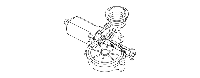
| *1 | Hall IC | *2 | Worm Gear |
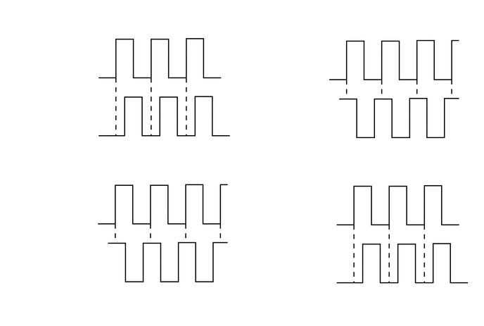
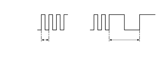
The Hall IC converts the changes in the magnetic flux that occur through the rotation of the worm gear into pulse signals and outputs them to the power window regulator master switch assembly.
To control the jam protection function, the power window regulator master switch assembly determines the amount of movement and the jamming of the window glass from the pulse signals from the Hall IC1, and the moving direction of the window glass from the phase difference between the pulses from the Hall IC1 and Hall IC2.