NM1840EF
_58
Vehicle Interior
_010370
HEATING / AIR CONDITIONING
_0055307
AIR CONDITIONING SYSTEM
DE
DETAILS
F
HEATING / AIR CONDITIONING AIR CONDITIONING SYSTEM DETAILS AIR CONDITIONING UNIT
CONSTRUCTION
a.
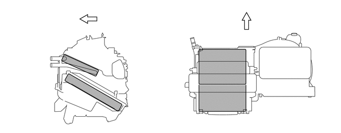
A semi-center location air conditioning unit is used, in which the evaporator and heater radiator are placed in the vehicle's longitudinal direction. As a result, the air conditioning unit has been made compact and lightweight.
1.458,1.25 1,0.792
true
1.5,1.667 0.781,1.667
true
4.313,1.167 3.75,1.167
true
4.313,2 3.75,2
true
0.833,0.635 1.104,0.896
0.271,0.26
10
false
*1
3.573,1.073 3.844,1.333
0.271,0.26
10
false
*1
0.583,1.583 0.875,1.875
0.292,0.292
10
false
*2
3.573,1.906 3.865,2.198
0.292,0.292
10
false
*2
1.469,0.292 1.802,0.604
0.333,0.313
10
false
*a
5.083,0.042 5.417,0.354
0.333,0.313
10
false
*a
| *1 | Heater Radiator Unit Sub-assembly | *2 | No. 1 Cooler Evaporator Sub-assembly |
| *a | Front | - | - |
b.
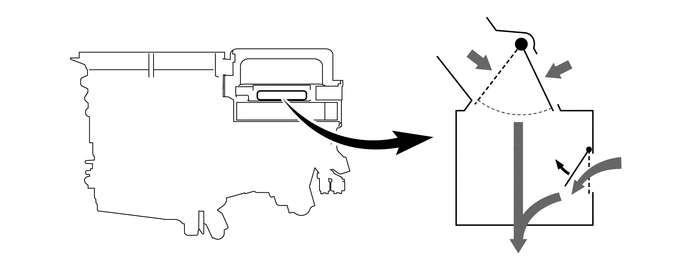
A partial recirculation system is used. This system has an air inlet control door (sub) in the air inlet duct. Thus, it is able to cycle a small volume of recirculated air even in the FRESH mode, thus enhancing heating performance. When the blower switch is on, the suction force of the blower fan opens this air inlet control door (sub).
5.573,0.75 5.688,0.354
true
6.021,1.698 6.021,1.063
6.021,1.063 6.25,1.063
true
5.656,0.198 5.896,0.438
0.24,0.24
10
false
*1
6.281,0.948 6.531,1.198
0.25,0.25
10
false
*2
4.708,0.313 5,0.542
0.292,0.229
10
false
*a
5.969,0.396 6.219,0.646
0.25,0.25
10
false
*b
6.5,1.542 6.75,1.792
0.25,0.25
10
false
*b
| *1 | Air Inlet Control Door | *2 | Air Inlet Control Door (Sub) |
| *a | Fresh Air | *b | Recirculated Air |
OPERATION
a.
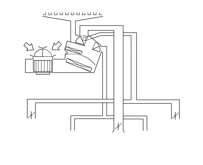
Mode Position and Damper Operation
1.396,2.417 1,2.802
true
2.75,2.333 2.719,2.74
true
2.823,1.844 5.042,2.219
true
2.135,0.094 3.167,0.438
1.031,0.344
10
false
Front Defroster
0.365,1.24 0.938,1.552
0.573,0.313
10
false
FRESH
1.844,1.167 2.448,1.5
0.604,0.333
10
false
RECIRC
0.396,2.802 1.792,3.469
1.396,0.667
10
false
Blower with Fan Motor Sub-assembly
2.031,2.76 3.51,3.427
1.479,0.667
10
false
No. 1 Cooler Evaporator Sub-assembly
5.083,2.083 6.344,2.813
1.26,0.729
10
false
Heater Radiator Unit Sub-assembly
0.698,4.219 1.583,4.698
0.885,0.479
10
false
Side Register
5.813,4.24 6.677,4.75
0.865,0.51
10
false
Side Register
2.042,4.625 3.125,5.26
1.083,0.635
10
false
Footwell Register Duct
4.771,4.635 5.865,5.26
1.094,0.625
10
false
Footwell Register Duct
3.938,4.708 4.49,5.323
0.552,0.615
10
false
Center Register
1.573,1.781 1.74,1.979
0.167,0.198
10
false
A
1.333,1.792 1.552,1.99
0.219,0.198
10
false
B
3.125,2.156 3.333,2.323
0.208,0.167
10
false
C
2.813,1.99 2.99,2.167
0.177,0.177
10
false
D
2.573,1.24 2.771,1.406
0.198,0.167
10
false
F
2.448,1.917 2.604,2.073
0.156,0.156
10
false
E
2.688,1.063 2.885,1.26
0.198,0.198
10
false
G
2.917,1.063 3.104,1.25
0.188,0.188
10
false
H
3.427,1.292 3.604,1.49
0.177,0.198
10
false
I
3.583,1.427 3.76,1.594
0.177,0.167
10
false
J
3.594,1.635 3.75,1.823
0.156,0.188
10
false
K
| Control Damper | Operation Position | Damper Position | Operation | |
|---|---|---|---|---|
| Air Inlet Control Damper | FRESH | A | Brings in fresh air. | |
| RECIRC | B | Recirculates internal air. | ||
| Air Mix Control Damper | MAX COLD to MAX HOT | C-D-E | Varies the mixture ratio of the cool air and the warm air in order to regulate the temperature continuously from HOT to COLD | |
| Mode Control Damper | FACE | 
|
F, K | Air blows out of the center registers and side register. |
| BI-LEVEL | 
|
F, J | Air blows out of the center registers, side registers and footwell register ducts. | |
| FOOT | 
|
G, I | Air blows out of the footwell register ducts and side register. In addition, air blows out slightly from the front defroster. | |
| FOOT/DEF | 
|
H, J | Defrosts the windshield through the front defroster and side register, while air is also blown out from the footwell register ducts. | |
| DEF | 
|
H, K | Defrosts the windshield through the front defroster and side register. | |
b.
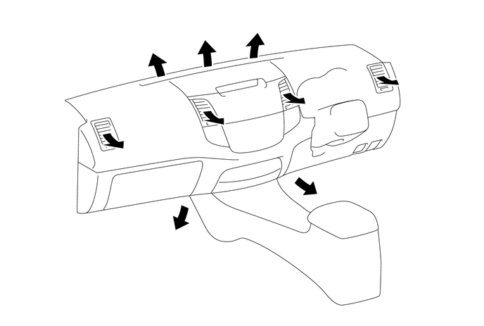
Air Outlets and Airflow Volume
3.365,1.844 3.531,2.031
0.167,0.188
10
false
A
5.958,1.208 6.125,1.396
0.167,0.188
10
false
B
1.833,2.219 2,2.406
0.167,0.188
10
false
B
4.781,2.833 4.948,3.021
0.167,0.188
10
false
C
2.51,3.479 2.677,3.667
0.167,0.188
10
false
C
2.167,0.573 2.333,0.76
0.167,0.188
10
false
D
2.948,0.396 3.115,0.583
0.167,0.188
10
false
D
3.74,0.271 3.906,0.458
0.167,0.188
10
false
D
4.573,1.458 4.74,1.646
0.167,0.188
10
false
A
| Indication | Mode | A | B | C | D |
|---|---|---|---|---|---|
| Center | Side | Footwell | Defroster | ||
|
|
FACE | 
|
|
- | - |
|
|
BI-LEVEL | 
|
|

|
- |
|
|
FOOT | - | 
|
|
|
|
|
FOOT/DEF | - |
|
|
|
|
|
DEF | - |
|
- |
|
- HINT:
-
The size of the circle ○ indicates the proportion of airflow volume.