2TR-FBE ENGINE CONTROL SFI SYSTEM P0201 Injector Circuit / Open - (Cylinder 1) P0202 Injector Circuit / Open - (Cylinder 2) P0203 Injector Circuit / Open - (Cylinder 3) P0204 Injector Circuit / Open - (Cylinder 4)
DESCRIPTION
The fuel injector assemblies are located on the intake manifold assembly. They inject fuel into the cylinders based on the signals from the ECM.
Reference: Inspection Using Oscilloscope
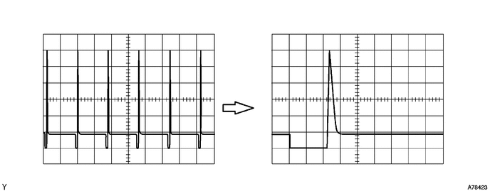
With the engine idling, check the waveform between terminals #10 to #40 and E01 of the ECM connectors.
- HINT:
-
The correct waveform is as shown in the diagram below.
| DTC No. | Detection Item | DTC Detection Condition | Trouble Area | MIL | Memory |
|---|---|---|---|---|---|
| P0201 | Injector Circuit / Open - (Cylinder 1) | Current is not applied to the injector more than 10 times with the engine running.
(1 trip detection logic) |
·
Open or short in fuel injector circuit ·
Fuel injector assembly ·
ECM |
Comes on | DTC stored |
| P0202 | Injector Circuit / Open - (Cylinder 2) | Current is not applied to the injector more than 10 times with the engine running.
(1 trip detection logic) |
·
Open or short in fuel injector circuit ·
Fuel injector assembly ·
ECM |
Comes on | DTC stored |
| P0203 | Injector Circuit / Open - (Cylinder 3) | Current is not applied to the injector more than 10 times with the engine running.
(1 trip detection logic) |
·
Open or short in fuel injector circuit ·
Fuel injector assembly ·
ECM |
Comes on | DTC stored |
| P0204 | Injector Circuit / Open - (Cylinder 4) | Current is not applied to the injector more than 10 times with the engine running.
(1 trip detection logic) |
·
Open or short in fuel injector circuit ·
Fuel injector assembly ·
ECM |
Comes on | DTC stored |
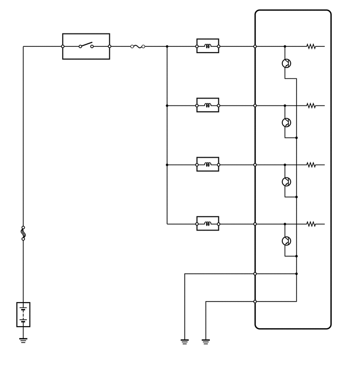
WIRING DIAGRAM
CAUTION / NOTICE / HINT
- HINT:
- ·
If DTC P0201 is set, check the No. 1 injector circuit.
·If DTC P0202 is set, check the No. 2 injector circuit.
·If DTC P0203 is set, check the No. 3 injector circuit.
·If DTC P0204 is set, check the No. 4 injector circuit.
·Read freeze frame data using the intelligent tester. The ECM records vehicle and driving condition information as freeze frame data the moment a DTC is stored. When troubleshooting, freeze frame data can help determine if the vehicle was moving or stationary, if the engine was warmed up or not, if the air fuel ratio was lean or rich, and other data from the time the malfunction occurred.
PROCEDURE
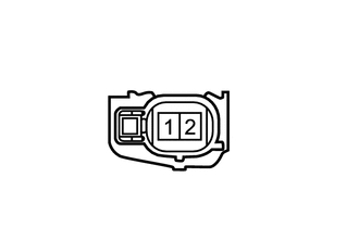
| *a | Front view of wire harness connector
(to Fuel Injector Assembly) |
Disconnect the fuel injector assembly connectors.
Turn the ignition switch to ON.
Measure the voltage according to the value(s) in the table below.
- Standard Voltage:
Tester Connection Switch Condition Specified Condition C65-1 - Body ground Ignition switch ON 11 to 14 V C2-1 - Body ground Ignition switch ON 11 to 14 V C66-1 - Body ground Ignition switch ON 11 to 14 V C4-1 - Body ground Ignition switch ON 11 to 14 V
Reconnect the fuel injector assembly connectors.
- Result:
Proceed to OK NG
OK
NG
Inspect the fuel injector assembly.
Click hereEngine / Hybrid System>2TR-FBE FUEL>FUEL INJECTOR>INSPECTION
- Result:
Proceed to OK NG
OK
NG
Disconnect the fuel injector assembly connectors.
Disconnect the ECM connector.
Measure the resistance according to the value(s) in the table below.
- Standard Resistance (Check for Open):
Tester Connection Condition Specified Condition C65-2 - C98-6 (#10) Always Below 1 Ω C2-2 - C98-7 (#20) Always Below 1 Ω C66-2 - C98-8 (#30) Always Below 1 Ω C4-2 - C98-9 (#40) Always Below 1 Ω
- Standard Resistance (Check for Short):
Tester Connection Condition Specified Condition C65-2 or C98-6 (#10) - Body ground Always 10 kΩ or higher C2-2 or C98-7 (#20) - Body ground Always 10 kΩ or higher C66-2 or C98-8 (#30) - Body ground Always 10 kΩ or higher C4-2 or C98-9 (#40) - Body ground Always 10 kΩ or higher
Reconnect the fuel injector assembly connectors.
Reconnect the ECM connector.
- Result:
Proceed to OK NG
OK
NG
Disconnect the ECM connectors.
Measure the resistance according to the value(s) in the table below.
- Standard Resistance (Check for Open):
Tester Connection Condition Specified Condition C98-11 (E01) - Body ground Always Below 1 Ω C98-12 (E02) - Body ground Always Below 1 Ω
Reconnect the ECM connectors.
- Result:
Proceed to OK NG
OK
NG