Home › Engine / Hybrid System › 1KD-FTV ENGINE MECHANICAL › CYLINDER BLOCK(w/ Glow Plug Controller) › from 2012.04
RM1840EF _51 Engine / Hybrid System _009573 1KD-FTV ENGINE MECHANICAL _0052162 CYLINDER BLOCK(w/ Glow Plug Controller) A

1KD-FTV ENGINE MECHANICAL  CYLINDER BLOCK(w/ Glow Plug Controller)  REPLACEMENT  


PROCEDURE

Hide 1.REPLACE CYLINDER BLOCK TIGHT PLUG

NOTICE:

If coolant leaks from a tight plug or a plug is corroded, replace it.


a.

Remove the cylinder block tight plugs.


b.

Apply adhesive to new cylinder block tight plugs.

Adhesive:

Toyota Genuine Adhesive 1324, Three Bond 1324 or equivalent


NOTICE:

Do not start the engine for 1 hour after installation.


c.

Position A:

Using a 14 mm steel bar and hammer, tap in the tight plug as shown in the illustration.


d.

Other positions:

Using SST and a hammer, tap in the tight plugs as shown in the illustration.

Position B

SST
09950-60010  (09951-00180)
09950-70010  (09951-07100)

Position C

SST
09950-60010  (09951-00190)
09950-70010  (09951-07100)

Position D

SST
09950-60010  (09951-00200)
09950-70010  (09951-07100)

Position E and H

SST
09950-60010  (09951-00350)
09950-70010  (09951-07100)

Position F

SST
09950-60010  (09951-00400, 09951-00450)
09950-70010  (09951-07100)

Position G

SST
09950-60010  (09951-00450)
09950-70010  (09951-07100)
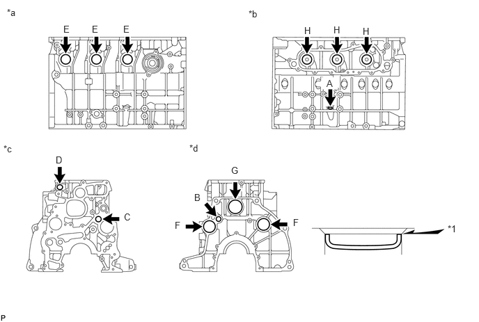
A303259C01
3.719,0.125 4.031,0.323 0.313,0.198 10 false *b 0.104,0.104 0.417,0.302 0.313,0.198 10 false *a 0.052,2.146 0.365,2.344 0.313,0.198 10 false *c 2.833,2.135 3.146,2.333 0.313,0.198 10 false *d 0.948,0.354 1.146,0.552 0.198,0.198 10 false E 1.375,0.354 1.573,0.552 0.198,0.198 10 false E 1.844,0.354 2.042,0.552 0.198,0.198 10 false E 4.99,0.365 5.219,0.615 0.229,0.25 10 false H 5.427,0.385 5.656,0.635 0.229,0.25 10 false H 4.552,0.375 4.781,0.625 0.229,0.25 10 false H 0.833,2.313 1.063,2.563 0.229,0.25 10 false D 1.854,3.167 2.083,3.417 0.229,0.25 10 false C 2.615,3.292 2.844,3.542 0.229,0.25 10 false F 2.906,2.875 3.135,3.125 0.229,0.25 10 false B 3.458,2.469 3.688,2.719 0.229,0.25 10 false G 4.385,3.25 4.615,3.5 0.229,0.25 10 false F 6.698,3.344 6.927,3.594 0.229,0.25 10 false *1 4.885,1.167 5.115,1.417 0.229,0.25 10 false A
*1 Stops - -
*a Right Side *b Left Side
*c Front Side *d Rear Side


Hide 2.REPLACE STRAIGHT PIN

NOTICE:

It is not necessary to remove a straight pin unless it is being replaced.


a.

Remove the straight pins.


b.

Using a plastic-faced hammer, tap in new straight pins to the cylinder block.

Standard Protrusion Height:
Item Specified Condition
Pin A 7.5 mm (0.295 in.) or less
Pin B 6 mm (0.234 in.) or less
Pin C 12 mm (0.472 in.) or less
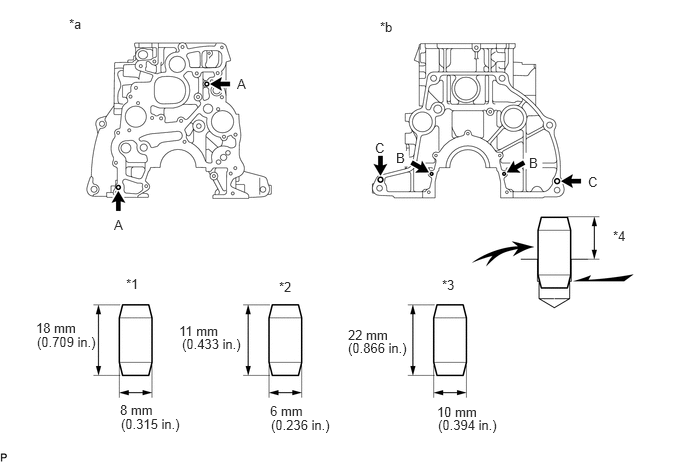

A303260C01
0.719,0.167 1.031,0.365 0.313,0.198 10 false *a 3.958,0.198 4.146,0.406 0.188,0.208 10 false *b 1.313,2.875 1.5,3.083 0.188,0.208 10 false *1 2.906,2.906 3.094,3.115 0.188,0.208 10 false *2 4.604,2.885 4.792,3.094 0.188,0.208 10 false *3 6.385,2.375 6.573,2.583 0.188,0.208 10 false *4 0.375,3.333 0.875,3.49 0.5,0.156 10 false 18 mm 0.385,3.479 1.094,3.667 0.708,0.188 10 false (0.709 in.) 1.26,4.333 1.969,4.521 0.708,0.188 10 false (0.315 in.) 1.865,3.365 2.365,3.521 0.5,0.156 10 false 11 mm 1.896,3.5 2.604,3.688 0.708,0.188 10 false (0.433 in.) 3.625,3.406 4.125,3.563 0.5,0.156 10 false 22 mm 3.625,3.542 4.333,3.729 0.708,0.188 10 false (0.866 in.) 1.25,4.188 1.75,4.344 0.5,0.156 10 false 8 mm 2.813,4.198 3.313,4.354 0.5,0.156 10 false 6 mm 2.823,4.344 3.531,4.531 0.708,0.188 10 false (0.236 in.) 4.552,4.208 5.052,4.365 0.5,0.156 10 false 10 mm 4.563,4.344 5.271,4.531 0.708,0.188 10 false (0.394 in.) 2.469,0.792 2.781,0.99 0.313,0.198 10 false A 1.188,2.26 1.5,2.458 0.313,0.198 10 false A 3.906,1.458 4.135,1.625 0.229,0.167 10 false C 4.125,1.563 4.354,1.729 0.229,0.167 10 false B 5.51,1.615 5.74,1.781 0.229,0.167 10 false B 6.125,1.813 6.354,1.979 0.229,0.167 10 false C
*1 Pin A *2 Pin B
*3 Pin C *4 Protrusion Height
*a Front Side *b Rear Side


Hide 3.REPLACE RING PIN

NOTICE:

It is not necessary to remove a ring pin unless it is being replaced.


a.

Remove the ring pins.


b.

Using a plastic-faced hammer, tap in new ring pins to the cylinder block.

Standard Protrusion:

6 mm (0.236 in.) or less
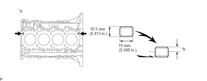

A256496C02
0.646,0.292 0.865,0.5 0.219,0.208 10 false *a 3.115,0.917 3.823,1.281 0.708,0.365 10 false 10.5 mm 4.104,1.49 4.792,1.854 0.688,0.365 10 false 15 mm 6.292,1.615 6.521,1.823 0.229,0.208 10 false *b 3.104,1.073 3.813,1.302 0.708,0.229 10 false (0.413 in.) 4.115,1.646 4.781,1.854 0.667,0.208 10 false (0.590 in.)
*a Cylinder Head Side *b 6 mm (0.236 in.) or less


Hide 4.REPLACE TURBO WATER HOSE UNION

NOTICE:

If coolant leaks from a turbo water hose union or a turbo water hose union is corroded, replace the turbo water hose union.


a.

Remove the turbo water hose union from the cylinder block.


b.

Clean the cylinder block side hole and new turbo water hose union with non-residue solvent.
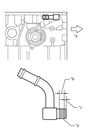

c.
A330616C01
2.198,3.333 2.333,2.833 2.333,2.833 2.5,2.833 false 2.323,3.552 2.667,3.844 2.667,3.844 2.792,3.844 true 2.198,4.198 2.542,4.49 2.542,4.49 2.667,4.49 true 2.646,1.198 2.875,1.354 0.229,0.156 10 false *a 2.531,2.729 2.781,2.896 0.25,0.167 10 false *b 2.823,3.75 3.052,3.906 0.229,0.156 10 false *c 2.698,4.396 2.927,4.563 0.229,0.167 10 false *d
*a Front
*b 5.0 mm (0.197 in.)
*c 2.0 mm (0.787 in.)
*d Adhesive


Apply adhesive onto the shaded area of a turbo water hose union as shown in the illustration.

Adhesive:

Toyota Genuine Adhesive 1324, Three Bond 1324 or equivalent


NOTICE:

Install the turbo water hose union within 3 minutes after applying adhesive.


d.

Set the turbo water hose union and tap it until the edge of the turbo water hose union fits against the chamfered part of the cylinder block as shown in the illustration.