Home › Engine / Hybrid System › 1GR-FE ENGINE MECHANICAL › CYLINDER HEAD › from 2012.04
RM1840EF _51 Engine / Hybrid System _009577 1GR-FE ENGINE MECHANICAL _0052212 CYLINDER HEAD A

1GR-FE ENGINE MECHANICAL  CYLINDER HEAD  REASSEMBLY  


PROCEDURE

Hide 1.INSTALL STUD BOLT

NOTICE:

If a stud bolt is deformed or its threads are damaged, replace it.


a.

Using E5 and E7 "TORX" sockets, install the stud bolts.

Torque:
for stud bolt A : 4.0 N*m (41 kgf*cm, 35 in.*lbf)
for stud bolt B : 9.5 N*m (97 kgf*cm, 84 in.*lbf)
for stud bolt C : 4.0 N*m (41 kgf*cm, 35 in.*lbf)
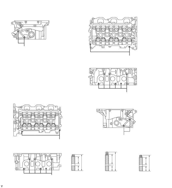
A158573
3.26,6.667 3.771,5.573 3.771,5.573 3.5,5.573 false 3.281,7.021 3.417,7.281 3.417,7.281 3.417,7.49 false 4.656,6.552 4.385,6 4.385,6 4.552,6 false 4.677,7.031 4.813,7.292 4.813,7.292 4.813,7.49 false 6.094,7.042 6.219,7.313 6.219,7.313 6.229,7.448 false 6.083,6.719 6.354,5.99 6.354,5.99 6.448,5.99 false 1.188,0.521 1.448,0.698 0.26,0.177 10 false *c 4.635,0.427 4.844,0.615 0.208,0.188 10 false *d 1.5,4.063 1.74,4.25 0.24,0.188 10 false *d 4.688,2.594 4.885,2.76 0.198,0.167 10 false *e 1.521,6.125 1.74,6.323 0.219,0.198 10 false *e 4.792,4.271 4.99,4.458 0.198,0.188 10 false *f 3.146,7.458 4.344,7.656 1.198,0.198 10 false 9.0 mm (0.354 in.) 3.438,6.656 4.042,7.052 0.604,0.396 10 false 33.3 mm (1.31 in.) 2.854,5.5 3.51,5.865 0.656,0.365 10 false 12.0 mm (0.472 in.) 4.594,5.917 5.865,6.125 1.271,0.208 10 false 20.0 mm (0.787 in.) 6.5,5.896 7.156,6.271 0.656,0.375 10 false 16.0 mm (0.630 in.) 4.875,6.563 5.469,6.938 0.594,0.375 10 false 42.0 mm (1.65 in.) 6.292,6.646 6.906,7.021 0.615,0.375 10 false 32.0 mm (1.26 in.) 4.51,7.469 5.792,7.667 1.281,0.198 10 false 13.0 mm (0.512 in.) 0.25,0.188 0.521,0.354 0.271,0.167 10 false *a 0.323,3.677 0.552,3.906 0.229,0.229 10 false *b 3.01,7.167 3.167,7.344 0.156,0.177 10 false A 4.396,7.177 4.552,7.354 0.156,0.177 10 false B 5.823,7.188 5.979,7.365 0.156,0.177 10 false C 2.438,5.833 2.594,6.01 0.156,0.177 10 false A 2.115,7.344 2.271,7.521 0.156,0.177 10 false B 5.115,5.667 5.271,5.844 0.156,0.177 10 false C 5.354,2.354 5.51,2.531 0.156,0.177 10 false A 5.24,3.875 5.396,4.052 0.156,0.177 10 false B 0.948,1.958 1.104,2.135 0.156,0.177 10 false C 5.948,7.417 7.146,7.615 1.198,0.198 10 false 9.0 mm (0.354 in.)
*a RH *b LH
*c Rear Side *d Upper Side
*e Exhaust Manifold Side - -


Hide 2.INSTALL NO. 2 STRAIGHT SCREW PLUG

NOTICE:

If coolant leaks from a straight screw plug or a plug is corroded, replace it.


a.

Using a 14 mm hexagon wrench, install 2 new gaskets and the 2 No. 2 straight screw plugs.

Torque:
85 N*m (867 kgf*cm, 63 ft.*lbf)


Hide 3.INSTALL NO. 1 STRAIGHT SCREW PLUG

NOTICE:

If coolant leaks from a straight screw plug or a plug is corroded, replace it.


a.

Using a 10 mm hexagon wrench, install 4 new gaskets and the 4 No. 1 straight screw plugs.

Torque:
80 N*m (816 kgf*cm, 59 ft.*lbf)


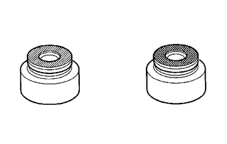
Hide 4.INSTALL VALVE STEM OIL SEAL

a.
A277095
0.667,0.698 0.927,0.427 0.927,0.427 1.115,0.427 false 2.51,0.688 2.802,0.406 2.802,0.406 2.979,0.406 false 1.177,0.365 1.49,0.563 0.313,0.198 10 *1 3.031,0.323 3.344,0.521 0.313,0.198 10 *2 0.646,1.688 0.958,1.885 0.313,0.198 10 *a 2.615,1.677 2.927,1.875 0.313,0.198 10 *b
*1 Brown
*2 Gray
*a Intake Side
*b Exhaust Side


Apply a light coat of engine oil to new valve stem oil seals.

NOTICE:

Pay attention when installing the intake and exhaust valve stem oil seals. For example, installing the intake valve stem oil seal to the exhaust side or installing the exhaust valve stem oil seal to the intake side can cause installation problems later.


HINT:

The intake valve stem oil seals are brown and the exhaust valve stem oil seals are gray.
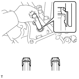


b.
A124592
1.396,0.677 0.781,0.135 0.781,0.135 0.458,0.135 true 1.021,2.177 1.49,2.479 0.469,0.302 10 false *a 2.25,2.167 2.667,2.427 0.417,0.26 10 false *b 0.104,0.063 0.875,0.417 0.771,0.354 10 false SST
*a CORRECT
*b INCORRECT


Using SST, push in the valve stem oil seals.

SST
09201-41020  

NOTICE:

Failure to use SST will cause the seal to be damaged or improperly seated.


Hide 5.INSTALL VALVE SPRING SEAT

a.

Install the valve spring seat.


Hide 6.INSTALL VALVE

a.
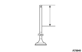
A075640
2.177,0.542 2.375,0.729 0.198,0.188 10 false *a
*a 35 mm (1.38 in.)


Apply plenty of engine oil to the tip of the valve shown in the illustration.


b.

Place the cylinder head on wooden blocks.
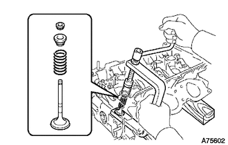

c.
A075602
2.313,0.729 2.313,0.375 2.313,0.375 2.167,0.375 false 2.802,1.625 2.708,1.708 false 1.75,0.302 2.063,0.479 0.313,0.177 10 false SST

Install the valve, inner compression spring and valve spring retainer to the cylinder head.

NOTICE:

Install the same parts in the same combination to their original locations.


d.

Using SST, compress the inner compression spring and install the 2 valve spring retainer locks.

SST
09202-70020  (09202-00010)


e.
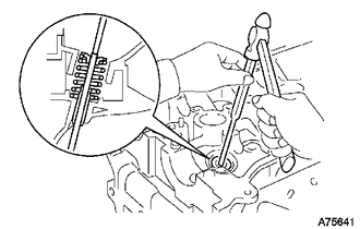
A075641

Using a 5 mm pin punch and hammer, lightly tap the valve stem tip to ensure a proper fit.

NOTICE:

Be careful not to damage the valve stem tip.