Home › Engine / Hybrid System › 1GR-FE ENGINE MECHANICAL › CYLINDER BLOCK › from 2012.04
RM1840EF _51 Engine / Hybrid System _009577 1GR-FE ENGINE MECHANICAL _0052213 CYLINDER BLOCK A

1GR-FE ENGINE MECHANICAL  CYLINDER BLOCK  REPLACEMENT  


PROCEDURE

Hide 1.REPLACE STRAIGHT PIN

NOTICE:

It is not necessary to remove a straight pin unless it is being replaced.


a.

Remove the straight pins.


b.

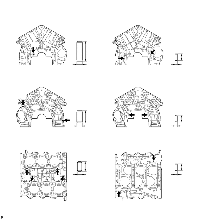
Using a plastic-faced hammer, tap in new straight pins to the cylinder block.

Standard Protrusion Height:
Item Specified Condition
Pin A 22.5 to 23.5 mm (0.886 to 0.925 in.)
Pin B 10.5 to 11.5 mm (0.413 to 0.453 in.)
Pin C 8.5 to 9.5 mm (0.335 to 0.374 in.)
Pin D 5.5 to 6.5 mm (0.217 to 0.256 in.)

A302412
6.5,2.042 7.104,1.625 7.104,1.625 6.917,1.625 false 3.073,4.208 3.781,3.844 3.781,3.844 3.49,3.844 false 3.052,5.979 3.76,5.615 3.76,5.615 3.552,5.615 false 6.5,5.99 7.115,5.625 7.115,5.625 6.948,5.625 false 6.51,4.25 7.125,3.875 7.125,3.875 6.958,3.875 false 0.271,0.885 0.583,1.042 0.313,0.156 10 false *a 0.302,3.417 0.615,3.573 0.313,0.156 10 false *b 3.823,5.521 4.135,5.677 0.313,0.156 10 false *d 3.948,0.979 4.26,1.135 0.313,0.156 10 false *a 3.813,3.344 4.125,3.5 0.313,0.156 10 false *b 0.25,5.438 0.563,5.594 0.313,0.156 10 false *c 1.146,1.5 1.458,1.656 0.313,0.156 10 false A 0.781,3.396 0.99,3.563 0.208,0.167 10 false B 2.531,4.219 2.74,4.385 0.208,0.167 10 false B 0.906,6.292 1.115,6.458 0.208,0.167 10 false C 1.156,6.135 1.365,6.302 0.208,0.167 10 false C 2,6.302 2.208,6.469 0.208,0.167 10 false C 2.24,6.125 2.448,6.292 0.208,0.167 10 false C 4.219,7.094 4.417,7.26 0.198,0.167 10 false D 5.469,5.385 5.667,5.552 0.198,0.167 10 false D 4.885,4.052 5.083,4.219 0.198,0.167 10 false D 4.094,1.99 4.292,2.156 0.198,0.167 10 false D 5.594,1.677 5.792,1.844 0.198,0.167 10 false D 3.094,1.719 4.177,1.906 1.083,0.188 10 false 36 mm (1.42 in.) 2.656,2.365 3.854,2.542 1.198,0.177 10 false 10 mm (0.394 in.) 5.771,1.542 6.917,1.729 1.146,0.188 10 false 12 mm (0.472 in.) 2.375,3.76 3.542,3.938 1.167,0.177 10 false 22 mm (0.866 in.) 2.396,5.531 3.688,5.698 1.292,0.167 10 false 18 mm (0.709 in.) 2.5,6.365 3.656,6.531 1.156,0.167 10 false 8 mm (0.315 in.) 5.771,2.406 6.844,2.594 1.073,0.188 10 false 4 mm (0.157 in.) 2.5,4.594 3.698,4.781 1.198,0.188 10 false 10 mm (0.394 in.) 5.896,6.344 7.021,6.531 1.125,0.188 10 false 4 mm (0.157 in.) 6.125,4.74 6.865,4.906 0.74,0.167 10 false (0.157 in.) 5.833,5.51 6.979,5.677 1.146,0.167 10 false 12 mm (0.472 in.) 6.146,4.552 6.646,4.719 0.5,0.167 10 false 4 mm 5.813,3.802 6.958,3.969 1.146,0.167 10 false 12 mm (0.472 in.)
*a Front Side *b Rear Side
*c Upper Side *d Lower Side


Hide 2.REPLACE CYLINDER BLOCK TIGHT PLUG

NOTICE:

If coolant leaks from a tight plug or a plug is corroded, replace it.


a.

Remove the tight plugs.


b.

Apply adhesive around new tight plugs.

Adhesive:

Toyota Genuine Adhesive 1324, Three Bond 1324 or equivalent


c.

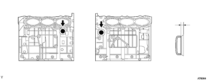
Using SST and a hammer, tap in the tight plugs to the standard depth.

SST
09950-60010  (09951-00350)
09950-70010  (09951-07150)

Standard depth:

0.2 to 1.2 mm (0.00787 to 0.0472 in.)

A076064
0.667,0.156 0.917,0.375 0.25,0.219 10 false *a 3.354,0.156 3.604,0.344 0.25,0.188 10 false *b 6.25,0.563 6.448,0.74 0.198,0.177 10 false *1
*1 Standard Depth - -
*a RH Side *b LH Side


Hide 3.REPLACE OIL JET

NOTICE:

It is not necessary to remove the oil jet unless it is being replaced.


a.

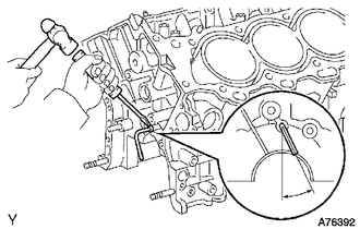
Using a screwdriver and hammer, tap out the oil jet.

b.
A076392
3.01,1.802 2.708,1.177 false 2.708,1.917 2.708,0.938 false 2.802,1.875 3.115,2.063 0.313,0.188 10 false *a
*a 26 to 27°


Using a screwdriver and hammer, tap in a new oil jet as shown in the illustration.