2KD-FTV FUEL FUEL SUPPLY PUMP(w/ DPF) INSTALLATION
CAUTION / NOTICE / HINT
- NOTICE:
- ·
When replacing the injectors (including shuffling the injectors between the cylinders), common rail or cylinder head, it is necessary to replace the injection pipes with new ones.
·When replacing the fuel supply pump, common rail, cylinder block, cylinder head, cylinder head gasket or timing gear case, it is necessary to replace the fuel inlet pipe with a new one.
·After removing the injection pipes and fuel inlet pipe, clean them with a brush and compressed air.
PROCEDURE

 1.INSTALL FUEL SUPPLY PUMP ASSEMBLY
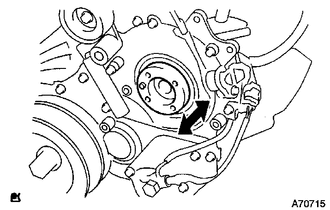
Check that the injection gear in the timing gear case moves back and forth smoothly.
Install a new O-ring to the fuel supply pump.
Apply a light coat of engine oil to the O-ring.
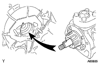
Align the groove of the injection gear with the set key on the drive shaft.
Install the fuel supply pump with the 2 nuts.
- Torque:
- 21 N*m (214 kgf*cm, 15 ft.*lbf)
Install a new O-ring before tightening the set nut.
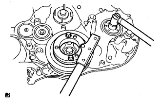
Using SST, hold the crankshaft pulley and install the set nut.
- SST
- 09213-58014
09330-00021
- Torque:
- 64 N*m (650 kgf*cm, 47 ft.*lbf)
Install the pump drive shaft pulley and No. 2 camshaft timing pulley flange with the 4 bolts.
- Torque:
- 31 N*m (316 kgf*cm, 23 ft.*lbf)
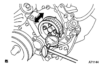
Move the pump drive shaft pulley back and forth to check the thrust clearance of the injection pump drive shaft.
- Standard thrust clearance:
0.15 to 0.55 mm (0.00590 to 0.0217 in.)
If the clearance is not within the specified range, disassemble and reassemble the fuel supply pump and pump drive shaft pulley. Then repeat the step above.
Connect the fuel temperature sensor connector and suction control valve connector to the fuel supply pump.
Connect the 2 fuel hoses.
2.INSTALL NO. 2 FUEL PIPE
3.INSTALL WIRING HARNESS CLAMP BRACKET
4.INSTALL NO. 4 INJECTION PIPE SUB-ASSEMBLY
5.INSTALL ELECTRIC EGR CONTROL VALVE ASSEMBLY WITH NO. 2 EGR VALVE AND EGR COOLER
6.INSTALL TIMING BELT
7.INSTALL RADIATOR ASSEMBLY
8.CONNECT CABLE TO NEGATIVE BATTERY TERMINAL
- NOTICE:
-
When disconnecting the cable, some systems need to be initialized after the cable is reconnected (See page General>INTRODUCTION>REPAIR INSTRUCTION>INITIALIZATION).
9.ADD ENGINE COOLANT
10.BLEED AIR FROM FUEL SYSTEM
11.PERFORM FUEL SUPPLY PUMP INITIALIZATION
12.INSPECT FOR COOLANT LEAK
13.INSPECT FOR FUEL LEAK