1KD-FTV EMISSION CONTROL EGR COOLER(w/ Glow Plug Controller) INSTALLATION
CAUTION / NOTICE / HINT
- NOTICE:
- ·
When replacing the injectors (including shuffling the injectors between the cylinders), common rail or cylinder head, it is necessary to replace the injection pipes with new ones.
·When replacing the fuel supply pump, common rail, cylinder block, cylinder head, cylinder head gasket or timing gear case, it is necessary to replace the fuel inlet pipe with a new one.
·After removing the injection pipes and fuel inlet pipe, clean them with a brush and compressed air.
PROCEDURE

 1.INSTALL EGR COOLER INSULATOR
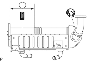
| *1 | No. 2 EGR Cooler Insulator |
| *2 | No. 1 EGR Cooler Insulator |
Install the 2 EGR cooler insulators to the EGR cooler.
- HINT:
- ·
Install the EGR cooler insulators so that they are positioned as shown in the illustration.
·Install the No. 2 EGR cooler insulator within the range labeled "A" in the illustration.
2.INSTALL NO. 2 EGR VALVE ASSEMBLY
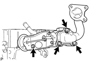
Using a 6 mm hexagon wrench, install 2 new gaskets, the EGR valve adapter, No. 2 EGR valve, EGR cooler and 3 plate washers with the 3 hexagon socket head cap bolts.
- Torque:
- 28 N*m (286 kgf*cm, 21 ft.*lbf)
Install the bolt labeled A.
- Torque:
- 13 N*m (133 kgf*cm, 10 ft.*lbf)
3.TEMPORARILY INSTALL INTAKE AIR CONNECTOR WITH ELECTRIC EGR CONTROL VALVE ASSEMBLY
4.TEMPORARILY INSTALL ELECTRIC EGR CONTROL VALVE ASSEMBLY WITH NO. 2 EGR VALVE AND EGR COOLER
Install a new gasket to the intake manifold.
Install a new gasket to the stud bolts of the cylinder head.
Set the electric EGR control valve with No. 2 EGR valve and EGR cooler on the intake manifold and cylinder head.
Temporarily install the intake air connector to the intake manifold with the 3 bolts labeled A in the illustration.
Temporarily install the EGR cooler to the intake manifold with the 2 bolts labeled B in the illustration.
Temporarily install the EGR cooler to the cylinder head with the 2 nuts labeled C in the illustration.
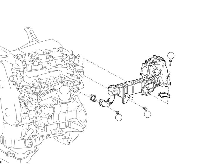
| *1 | New Gasket | *2 | Intake Manifold |
| *3 | Intake Air Connector | *4 | EGR Cooler |
5.TIGHTEN ELECTRIC EGR CONTROL VALVE ASSEMBLY WITH NO. 2 EGR VALVE AND EGR COOLER
Tighten the 3 bolts labeled A in the illustration.
- Torque:
- 20 N*m (204 kgf*cm, 15 ft.*lbf)
Tighten the 2 bolts labeled B in the illustration.
- Torque:
- 22 N*m (224 kgf*cm, 16 ft.*lbf)
Tighten the 2 nuts labeled C in the illustration.
- Torque:
- 13 N*m (133 kgf*cm, 10 ft.*lbf)
Temporarily install the EGR valve bracket with the 3 bolts.
Tighten the bolt labeled D in the illustration.
- Torque:
- 20 N*m (204 kgf*cm, 15 ft.*lbf)
Tighten the 2 bolts labeled E in the illustration.
- Torque:
- 20 N*m (204 kgf*cm, 15 ft.*lbf)
Tighten the 3 nuts labeled F in the illustration.
- Torque:
- 24 N*m (245 kgf*cm, 18 ft.*lbf)
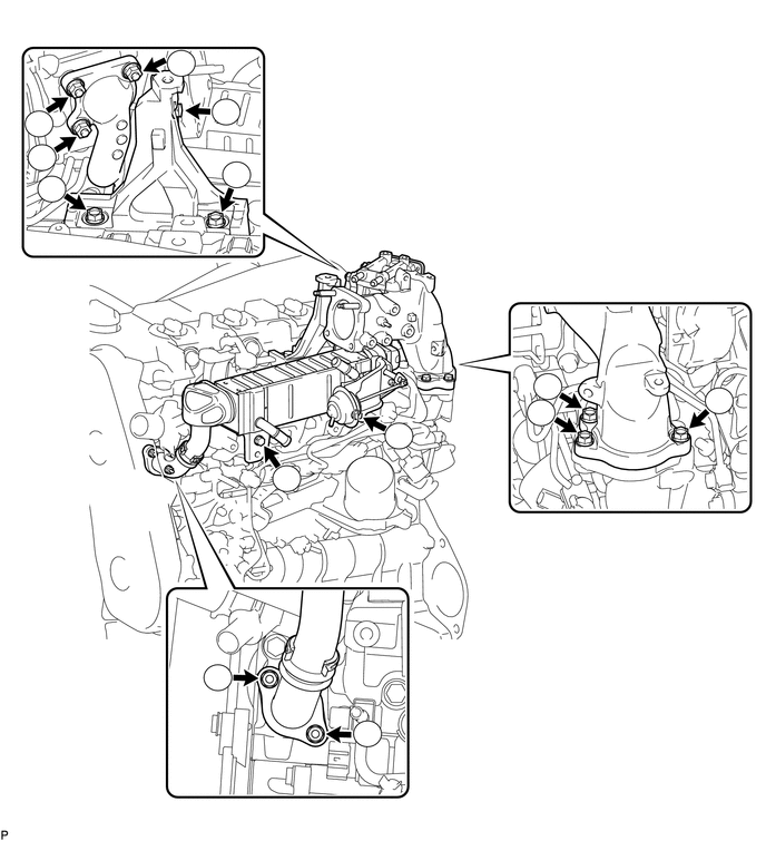
| *1 | EGR Valve Bracket | - | - |
for DPF:
Connect the fuel pressure sensor connector to the common rail.
6.CONNECT NO. 3 WATER BY-PASS PIPE
Connect the No. 3 water by-pass pipe with the 2 bolts.
- Torque:
- 18 N*m (184 kgf*cm, 13 ft.*lbf)
7.CONNECT ENGINE WIRE
Connect the engine wire with the bolt.
- Torque:
- 13 N*m (128 kgf*cm, 9 ft.*lbf)
Attach the 2 wire harness clamps.
8.INSTALL THROTTLE BODY BRACKET
Install the throttle body bracket with the 3 bolts.
- Torque:
- 20 N*m (204 kgf*cm, 15 ft.*lbf)
9.INSTALL WIRING HARNESS CLAMP BRACKET
Install the wiring harness clamp bracket with the bolt.
- Torque:
- 13 N*m (128 kgf*cm, 9 ft.*lbf)
10.INSTALL GAS FILTER BRACKET WITH GAS FILTER
Install the gas filter bracket with gas filter with the bolt.
- Torque:
- 8.0 N*m (82 kgf*cm, 71 in.*lbf)
Connect the vacuum hose.
11.INSTALL MANIFOLD ABSOLUTE PRESSURE SENSOR
Install the manifold absolute pressure sensor with the bolt.
- Torque:
- 8.0 N*m (82 kgf*cm, 71 in.*lbf)
Connect the vacuum hose and manifold absolute pressure sensor connector.
12.INSTALL NO. 5 WATER BY-PASS PIPE
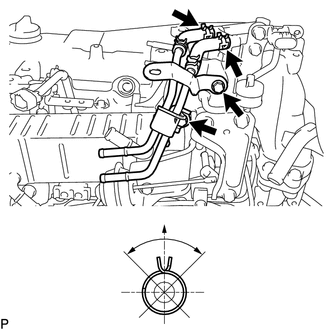
| *a | Upper Side |
Install the No. 5 water by-pass pipe with the 2 bolts.
- Torque:
- 20 N*m (204 kgf*cm, 15 ft.*lbf)
Connect the 2 water hoses to the electric EGR control valve.
- HINT:
- ·
Push the water hoses on until they contact the body of the electric EGR control valve.
·The direction of the hose clamps is indicated in the illustration.
Attach the 2 wire harness clamps.
13.INSTALL NO. 1, NO. 2 AND NO. 3 INJECTION PIPE SUB-ASSEMBLY
- NOTICE:
- ·
When replacing an injector, it is necessary to replace the 4 injection pipes with new ones.
·Keep the joints of the injection pipe clean.
Temporarily install the No. 1, No. 2 and No. 3 injection pipes with the union nuts.
Install the 2 No. 3 injection pipe clamps with the 4 nuts.
- Torque:
- 5.0 N*m (51 kgf*cm, 44 in.*lbf)
Using a 17 mm union nut wrench, tighten the injection pipe union nuts on the common rail side.
- Torque:
- 35 N*m (357 kgf*cm, 26 ft.*lbf)
- NOTICE:
-
Use the formula to calculate special torque values for situations where a union nut wrench is combined with a torque wrench (See page General>INTRODUCTION>REPAIR INSTRUCTION>PRECAUTION).
Using a 17 mm union nut wrench, tighten the injection pipe union nuts on the injector side.
- Torque:
- 35 N*m (357 kgf*cm, 26 ft.*lbf)
- NOTICE:
-
Use the formula to calculate special torque values for situations where a union nut wrench is combined with a torque wrench (See page General>INTRODUCTION>REPAIR INSTRUCTION>PRECAUTION).
14.INSTALL FUEL INLET PIPE SUB-ASSEMBLY
Temporarily install the fuel inlet pipe with the union nuts.
- NOTICE:
- ·
When replacing the fuel supply pump, it is necessary to replace the fuel inlet pipe with a new one.
·Keep the fuel inlet pipe free of foreign matter.
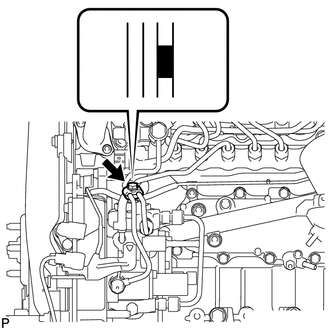
| *1 | Fuel Inlet Pipe |
| *2 | Paint Mark |
| *3 | No. 2 Fuel Pipe |
Install the No. 2 injection pipe clamp with the bolt.
- Torque:
- 5.0 N*m (51 kgf*cm, 44 in.*lbf)
- HINT:
-
When installing the No. 2 injection pipe clamp, align it with the paint mark of the fuel inlet pipe shown in the illustration.
Using a 17 mm union nut wrench, tighten the fuel inlet pipe union nut on the common rail side.
- Torque:
- 35 N*m (357 kgf*cm, 26 ft.*lbf)
- NOTICE:
-
Use the formula to calculate special torque values for situations where a union nut wrench is combined with a torque wrench (See page General>INTRODUCTION>REPAIR INSTRUCTION>PRECAUTION).
Using a 17 mm union nut wrench, tighten the fuel inlet pipe union nut on the fuel supply pump side.
- Torque:
- 35 N*m (357 kgf*cm, 26 ft.*lbf)
- NOTICE:
-
Use the formula to calculate special torque values for situations where a union nut wrench is combined with a torque wrench (See page General>INTRODUCTION>REPAIR INSTRUCTION>PRECAUTION).
15.INSTALL NO. 3 CYLINDER HEAD COVER SUB-ASSEMBLY (for DPF)
Install the No. 3 cylinder head cover with the 3 bolts.
- Torque:
- 8.0 N*m (82 kgf*cm, 71 in.*lbf)
16.INSTALL FUEL PIPE INSULATOR (for i-ART)
Install the fuel pipe insulator to the fuel pipes.
17.INSTALL VACUUM SWITCHING VALVE
Install the vacuum switching valve to the manifold stay with the screw.
Connect the 2 vacuum hoses to the vacuum switching valve.
18.INSTALL MANIFOLD STAY WITH VACUUM SWITCHING VALVE
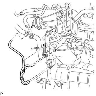
| *1 | No. 2 Vacuum Transmitting Hose |
| *2 | White Paint Mark |
Install the manifold stay with vacuum switching valve with the 2 bolts.
- Torque:
- 19 N*m (194 kgf*cm, 14 ft.*lbf)
Connect the 2 vacuum hoses.
Connect the vacuum switching valve connector.
19.CONNECT WATER BY-PASS HOSE
Connect the 6 water by-pass hoses.
- HINT:
- ·
When connecting the hoses, make sure the paint marks and clamps are as shown in the illustration.
·The direction of each hose clamp is indicated in the illustration.
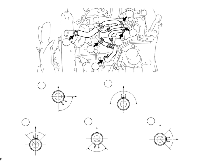
| *1 | Paint Mark | - | - |
| *a | Upper Side | *b | LH Side |
20.INSTALL ENGINE OIL LEVEL DIPSTICK GUIDE
Install a new O-ring to the engine oil level dipstick guide.
Apply a small amount of clean engine oil to the O-ring.
Install the engine oil level dipstick guide with the bolt.
- Torque:
- 8.0 N*m (82 kgf*cm, 71 in.*lbf)
Attach the wire harness clamp.
for DPF:
Install the engine oil level dipstick.
for i-ART:
Install the engine oil level dipstick and gasket.
21.INSTALL FRONT FENDER SEAL
Install the front fender seal with the 5 clips.
22.INSTALL FRONT FENDER APRON SEAL UPPER
Install the front fender apron seal upper with the 5 clips.
23.INSTALL FRONT WHEEL LH
24.INSTALL DIESEL THROTTLE BODY ASSEMBLY
25.CONNECT CABLE TO NEGATIVE BATTERY TERMINAL
- NOTICE:
-
When disconnecting the cable, some systems need to be initialized after the cable is reconnected (See page General>INTRODUCTION>REPAIR INSTRUCTION>INITIALIZATION).
26.ADD ENGINE COOLANT
27.BLEED AIR FROM FUEL SYSTEM
28.INSPECT FOR COOLANT LEAK
29.INSPECT FOR FUEL LEAK
30.INSTALL NO. 1 ENGINE UNDER COVER