RM1840EF
_51
Engine / Hybrid System
_009608
CRUISE CONTROL
_0052446
CRUISE CONTROL SYSTEM
U
CRUISE CONTROL CRUISE CONTROL SYSTEM TERMINALS OF ECM
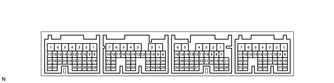
CHECK ECM (except i-ART)
5.448,0.229 5.854,0.438
0.406,0.208
4.146,0.229 4.552,0.438
0.406,0.208
2.74,0.229 3.146,0.438
0.406,0.208
1.333,0.229 1.74,0.438
0.406,0.208
1.427,0.26 1.823,0.51
0.396,0.25
10
false
C22
5.531,0.26 5.875,0.427
0.344,0.167
10
false
G39
2.833,0.26 3.208,0.51
0.375,0.25
10
false
C23
4.229,0.26 4.719,0.531
0.49,0.271
10
false
G38
a.
Disconnect the C23, G38 and G39 ECM connectors.
b.
Measure the voltage and resistance according to the value(s) in the table below.
| Terminal No. (Symbol) | Wiring Color | Terminal Description | Condition | Specified Condition |
|---|---|---|---|---|
| G38-2 (BATT) - C23-7 (E1) | L - BR | Battery | Always | 11 to 14 V |
| G39-9 (IGSW) - C23-7 (E1) | B-O - BR | IG power supply | Ignition switch ON | 11 to 14 V |
| Ignition switch off | Below 1 V | |||
| G38-15 (STP) - C23-7 (E1) | G-W - BR | Stop light switch input signal | Brake pedal released | Below 1 V |
| Brake pedal depressed | 11 to 14 V | |||
| G38-14 (ST1-) - C23-7 (E1) | R-L - BR | Cruise cancel input signal | Ignition switch ON
Brake pedal depressed |
Below 1 V |
| Ignition switch ON
Brake pedal released |
11 to 14 V | |||
| C23-7 (E1) - Body ground | BR - Body ground | Ground | Always | Below 1 Ω |
c.
Reconnect the C23, G38 and G39 ECM connectors.
d.
Measure the voltage according to the value(s) in the table below.
| Terminal No. (Symbol) | Wiring Color | Terminal Description | Condition | Specified Condition |
|---|---|---|---|---|
| G39-21 (CCS) - C23-7 (E1) | G-W - BR | Cruise control main switch signal | Ignition switch ON | 11 to 14 V |
| Ignition switch ON
CANCEL switch held on |
6.6 to 10.1 V | |||
| Ignition switch ON
-SET switch held on |
4.5 to 7.1 V | |||
| Ignition switch ON
+RES switch held on |
2.3 to 4.0 V | |||
| Ignition switch ON
Cruise control main switch on |
Below 1 V | |||
| G38-3 (P1) - C23-7 (E1) | L-B - BR | Cruise main indicator light input signal | Ignition switch ON
Cruise control main switch on |
Below 1 V |
| G38-3 (P1) - C23-7 (E1) | L-B - BR | Cruise control main switch signal | Ignition switch ON
Cruise control main switch off |
11 to 14 V |
| G39-11 (TC) - C23-7 (E1) | P-B - BR | Terminal TC of DLC3 | Ignition switch ON | 9 to 14 V |
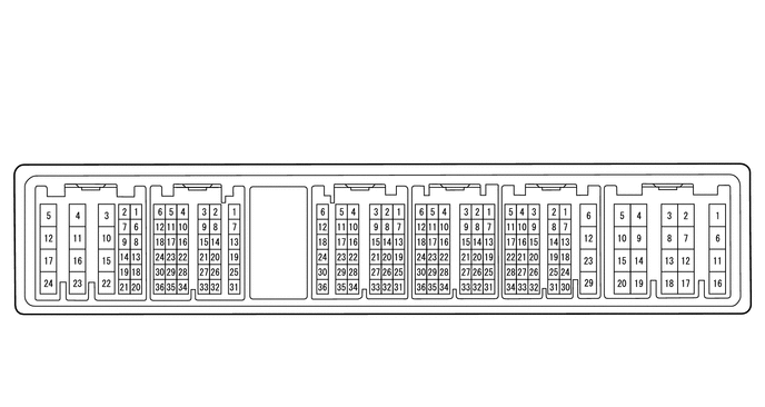
CHECK ECM (for i-ART)
0.625,0.719 1.104,0.979
0.479,0.26
1.594,0.719 2.073,0.979
0.479,0.26
3.198,0.719 3.677,0.979
0.479,0.26
4.031,0.719 4.51,0.979
0.479,0.26
4.938,0.719 5.417,0.979
0.479,0.26
6.031,0.719 6.51,0.979
0.479,0.26
0.698,0.781 1.271,1.021
0.573,0.24
10
false
G157
1.667,0.781 2.25,1.073
0.583,0.292
10
false
G156
3.281,0.781 3.865,1.083
0.583,0.302
10
false
C166
4.115,0.781 4.708,1.083
0.594,0.302
10
false
C167
5.031,0.771 5.635,1.073
0.604,0.302
10
false
C163
6.125,0.771 6.719,1.063
0.594,0.292
10
false
C164
a.
Disconnect the C164, G157 and G158 ECM connectors.
b.
Measure the voltage and resistance according to the value(s) in the table below.
| Terminal No. (Symbol) | Wiring Color | Terminal Description | Condition | Specified Condition |
|---|---|---|---|---|
| G157-23 (BATT) - C164-6 (E1) | L - BR | Battery | Always | 11 to 14 V |
| G158-24 (IGSW) - C164-6 (E1) | B-O - BR | IG power supply | Ignition switch ON | 11 to 14 V |
| Ignition switch off | Below 1 V | |||
| G157-8 (STP) - C164-6 (E1) | G-W - BR | Stop light switch input signal | Brake pedal released | Below 1 V |
| Brake pedal depressed | 11 to 14 V | |||
| G157-9 (ST1-) - C164-6 (E1) | R-L - BR | Cruise cancel input signal | Ignition switch ON
Brake pedal depressed |
Below 1 V |
| Ignition switch ON
Brake pedal released |
11 to 14 V | |||
| C164-6 (E1) - Body ground | BR - Body ground | Ground | Always | Below 1 Ω |
c.
Reconnect the C164, G157 and G158 ECM connectors.
d.
Measure the voltage according to the value(s) in the table below.
| Terminal No. (Symbol) | Wiring Color | Terminal Description | Condition | Specified Condition |
|---|---|---|---|---|
| G157-14 (CCS) - C164-6 (E1) | G-W - BR | Cruise control main switch signal | Ignition switch ON | 11 to 14 V |
| Ignition switch ON
CANCEL switch held on |
6.6 to 10.1 V | |||
| Ignition switch ON
-SET switch held on |
4.5 to 7.1 V | |||
| Ignition switch ON
+RES switch held on |
2.3 to 4.0 V | |||
| Ignition switch ON
Cruise control main switch on |
Below 1 V | |||
| G156-34 (P1) - C164-6 (E1) | L-B - BR | Cruise main indicator light input signal | Ignition switch ON
Cruise control main switch on |
Below 1 V |
| G156-34 (P1) - C164-6 (E1) | L-B - BR | Cruise control main switch signal | Ignition switch ON
Cruise control main switch off |
11 to 14 V |
| G156-23 (TC) - C164-6 (E1) | P-B - BR | Terminal TC of DLC3 | Ignition switch ON | 9 to 14 V |