A340F AUTOMATIC TRANSMISSION / TRANSAXLE AUTOMATIC TRANSMISSION UNIT DISASSEMBLY
PROCEDURE

 1.REMOVE DRAIN PLUG
Remove the drain plug and gasket.
2.REMOVE BREATHER HOSE
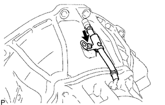
Remove the bolt and breather hose.
3.REMOVE TRANSMISSION CONTROL SHAFT LEVER LH
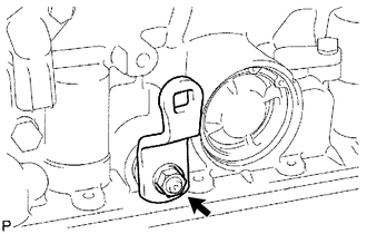
Remove the nut, washer and control shaft lever.
4.REMOVE PARK/NEUTRAL POSITION SWITCH ASSEMBLY
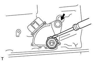
| *1 | Lock Washer |
| *2 | Lock Nut |
Using a screwdriver, bend the tabs of the lock washer.
Remove the lock nut and lock washer.
Remove the bolt and park/neutral position switch.
- HINT:
-
Make sure that the manual valve lever shaft has not been rotated prior to installing the park/neutral position switch as the detent spring may become detached from the manual valve lever shaft.
5.REMOVE ATF TEMPERATURE SENSOR
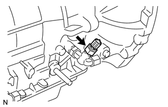
Remove the sensor.
6.REMOVE OIL COOLER TUBE UNION
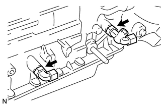
Remove the 2 tube unions.
Remove the O-ring from each tube union.
7.REMOVE SPEED SENSOR NC0
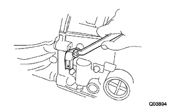
Remove the bolt and sensor.
Remove the O-ring from the sensor.
8.REMOVE SPEED SENSOR SP2
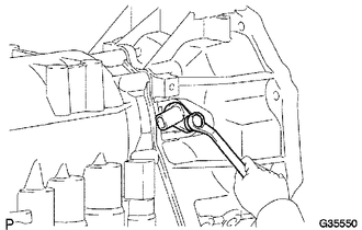
Remove the bolt and sensor.
Remove the O-ring from the sensor.
9.REMOVE AUTOMATIC TRANSMISSION HOUSING
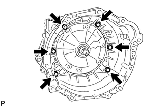
Remove the 6 bolts.
Remove the transmission housing.
10.SECURE TRANSMISSION CASE
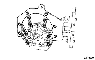
Secure the transmission case to an overhaul attachment.
11.REMOVE REAR TRANSFER ADAPTER
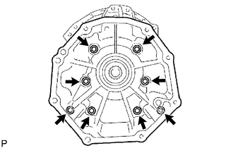
Remove the 8 bolts.
Remove the extension housing and gasket.
12.REMOVE TRANSFER CASE ADAPTER REAR OIL SEAL
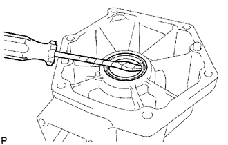
| *1 | Protective Tape |
Using a screwdriver, pry out the oil seal.
- NOTICE:
-
Do not damage the rear transfer adapter.
- HINT:
-
Tape the screwdriver tip before use.
13.REMOVE TRANSFER CASE REAR ADAPTER OIL RECEIVER
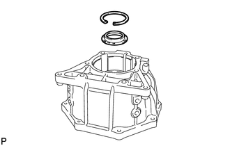
Using snap ring expander, remove the snap ring.
Remove the transfer case rear adaptor oil receiver from the rear transfer adaptor.
14.REMOVE SENSOR ROTOR
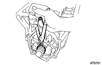
Using a snap ring expander, remove the snap ring.
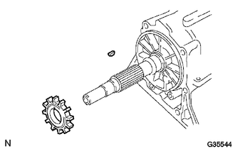
| *1 | Key |
| *2 | Sensor Rotor |
Remove the sensor rotor and key.
15.REMOVE AUTOMATIC TRANSMISSION OIL PAN SUB-ASSEMBLY
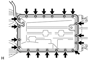
- NOTICE:
-
Do not turn the transmission over as this will contaminate the valve body with foreign matter located at the bottom of the oil pan.
Remove the 19 bolts.
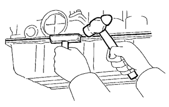
Insert the blade of an oil pan seal cutter between the transmission case and oil pan, and then cut through the applied sealer.
- NOTICE:
-
Be careful not to damage the flanges of the oil pan and transmission case.
Remove the oil pan from the transmission case.
16.INSPECT AUTOMATIC TRANSMISSION OIL PAN SUB-ASSEMBLY
17.REMOVE VALVE BODY OIL STRAINER ASSEMBLY
Turn over the transmission.
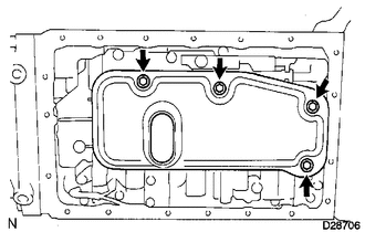
Remove the 4 bolts and valve body oil strainer from the valve body.
Remove the 3 gaskets from the oil strainer.
18.REMOVE TRANSMISSION WIRE
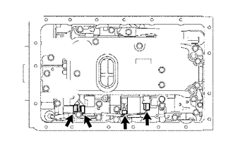
Disconnect the 4 connectors from the shift solenoid valves.
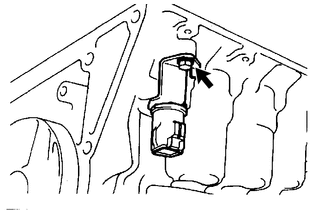
Remove the bolt.
Pull out the transmission wire from the transmission case to remove it.
Remove the O-ring from the transmission wire connector.
19.REMOVE TRANSMISSION VALVE BODY ASSEMBLY
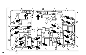
Remove the 20 bolts and valve body.
20.REMOVE CHECK BALL BODY
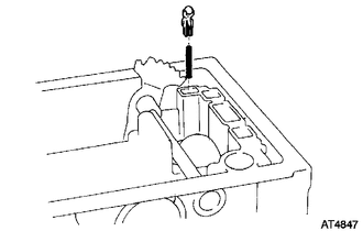
| *1 | Check Ball Body |
| *2 | Spring |
Remove the check ball body and spring.
21.REMOVE B-2 ACCUMULATOR PISTON
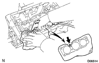
Apply compressed air (392 kPa, 4.0 kgf/cm2, 57 psi) to the oil hole to remove the B-2 accumulator piston and spring.
- NOTICE:
- ·
The application of compressed air may cause the piston to jump out. When removing the piston, hold it using a piece of cloth.
·Take care not to splash ATF when applying the compressed air.
Remove the 2 O-rings from the piston.
22.REMOVE C-2 ACCUMULATOR PISTON
Apply compressed air (392 kPa, 4.0 kgf/cm2, 57 psi) to the oil hole to remove the C-2 accumulator piston and 2 springs.
- NOTICE:
- ·
The application of compressed air may cause the piston to jump out. When removing the piston, hold it using a piece of cloth.
·Take care not to splash ATF when applying the compressed air.
Remove the 2 O-rings from the piston.
23.REMOVE B-0 ACCUMULATOR PISTON
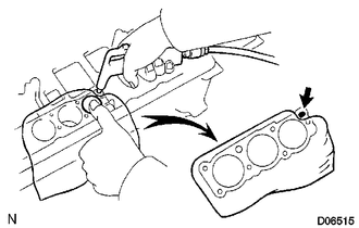
Apply compressed air (392 kPa, 4.0 kgf/cm2, 57 psi) to the oil hole to remove the B-0 accumulator piston and spring.
- NOTICE:
- ·
The application of compressed air may cause the piston to jump out. When removing the piston, hold it using a piece of cloth.
·Take care not to splash ATF when applying the compressed air.
Remove the 2 O-rings from the piston.
24.REMOVE C-0 ACCUMULATOR PISTON
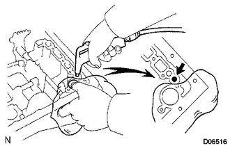
Apply compressed air (392 kPa, 4.0 kgf/cm2, 57 psi) to the oil hole to remove the C-0 accumulator piston and 2 springs.
- NOTICE:
- ·
The application of compressed air may cause the piston to jump out. When removing the piston, hold it using a shop rag or piece of cloth.
·Take care not to splash ATF when applying the compressed air.
Remove the O-ring from the piston.
25.REMOVE PARKING LOCK PAWL BRACKET
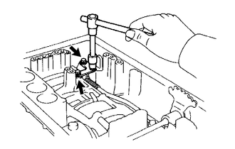
Remove the 3 bolts and bracket.
26.REMOVE PARKING LOCK ROD SUB-ASSEMBLY
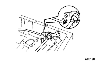
Disconnect the parking lock rod from the manual valve lever to remove it.
27.REMOVE PARKING LOCK PAWL
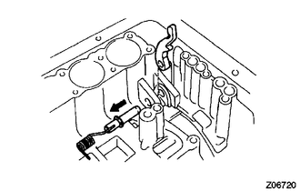
| *1 | Parking Lock Pawl Shaft |
| *2 | Lock Pawl |
| *3 | Spring |
| *4 | E-Ring |
Pull out the parking lock pawl shaft from the front side, and then remove the lock pawl and spring.
Remove the E-ring from the shaft.
28.REMOVE MANUAL VALVE LEVER SHAFT
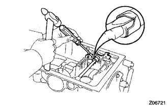
| *1 | Spacer |
| *2 | Protective Tape |
Using a hammer and screwdriver, cut off the spacer and remove it from the shaft.
- NOTICE:
-
Be careful not to damage the manual valve lever shaft.
- HINT:
-
Tape the screwdriver tip before use.
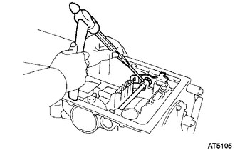
Using a pin punch and hammer, tap out the spring pin.
- HINT:
-
Tap out the spring pin slowly so that it does not fall into the transmission case.
Pull out the manual valve lever shaft through the case and remove the manual valve lever.
29.REMOVE MANUAL VALVE LEVER SHAFT OIL SEAL
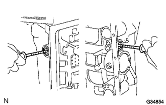
| *1 | Protective Tape |
Using a screwdriver, pry out the 2 oil seals.
- NOTICE:
-
Be careful not to damage the transmission case.
- HINT:
-
Tape the screwdriver tip before use.
30.REMOVE OIL PUMP ASSEMBLY
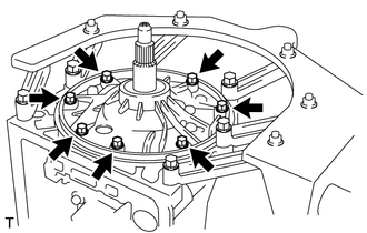
Stand the transmission upright.
Remove the 7 bolts from the transmission case.
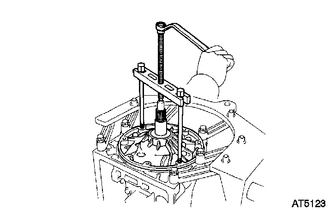
Using SST, remove the oil pump assembly.
- SST
- 09350-30020 (09350-07020)
Remove the O-ring from the oil pump assembly.
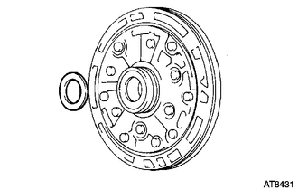
Remove the bearing race from the oil pump assembly.
31.REMOVE OVERDRIVE PLANETARY GEAR ASSEMBLY WITH OVERDRIVE DIRECT CLUTCH AND OVERDRIVE 1-WAY CLUTCH ASSEMBLY
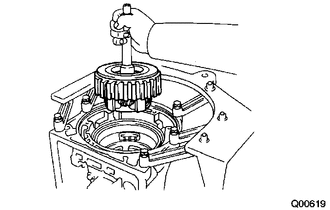
Remove the planetary gear together with the direct clutch and 1-way clutch from the transmission case.
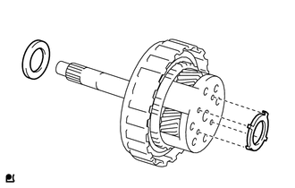
| *1 | Bearing Race |
| *2 | Bearing |
Remove the bearing race and bearing.
32.INSPECT OVERDRIVE 1-WAY CLUTCH
33.REMOVE OVERDRIVE DIRECT CLUTCH DRUM ASSEMBLY
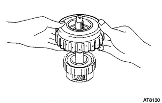
34.REMOVE OVERDRIVE DIRECT CLUTCH DISC SET
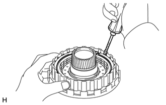
| *1 | Protective Tape |
Using a screwdriver, pry out the snap ring from the overdrive direct clutch drum.
- NOTICE:
-
Be careful not to damage the overdrive direct clutch drum.
- HINT:
-
Tape the screwdriver tip before use.
Remove the flange, 2 discs and 2 plates.
35.INSPECT OVERDRIVE DIRECT CLUTCH DISC
36.REMOVE OVERDRIVE DIRECT CLUTCH RETURN SPRING SUB-ASSEMBLY
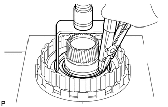
Place SST on the return spring and compress the return spring with a press.
- SST
- 09350-30020 (09350-07040)
Using SST, remove the snap ring.
- SST
- 09350-30020 (09350-07070)
Remove the clutch return spring.
37.INSPECT OVERDRIVE DIRECT CLUTCH RETURN SPRING SUB-ASSEMBLY
38.REMOVE OVERDRIVE DIRECT CLUTCH PISTON SUB-ASSEMBLY
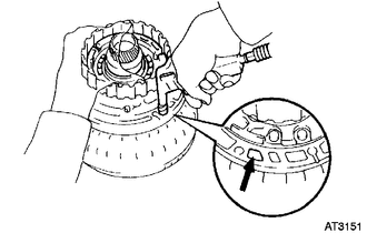
Place the oil pump onto the torque converter, and then place the overdrive direct clutch onto the oil pump.
Hold the overdrive direct clutch piston by hand and apply compressed air (392 kPa (4.0 kgf/cm2, 57 psi)) to the oil pump to remove the overdrive direct clutch piston.
- HINT:
-
If the piston is at an angle and cannot be removed, press down on the protruding side and apply compressed air again.
Remove the 2 O-rings from the piston.
39.INSPECT OVERDRIVE DIRECT CLUTCH PISTON SUB-ASSEMBLY
40.INSPECT OVERDRIVE DIRECT CLUTCH DRUM SUB-ASSEMBLY
41.REMOVE OVERDRIVE RETAINING PLATE
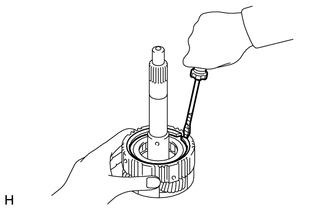
| *1 | Protective Tape |
Using a screwdriver, pry out the snap ring.
- NOTICE:
-
Be careful not to damage the overdrive planetary gear assembly and the plate.
- HINT:
-
Tape the screwdriver tip before use.
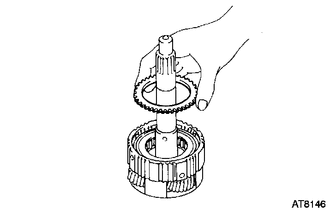
Remove the retaining plate.
42.REMOVE OVERDRIVE 1-WAY CLUTCH OUTER RACE WITH OVERDRIVE 1-WAY CLUTCH
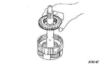
43.REMOVE OVERDRIVE 1-WAY CLUTCH
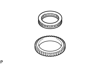
Remove the overdrive 1-way clutch from the outer race.
44.REMOVE NO. 3 OVERDRIVE PLANETARY GEAR THRUST WASHER
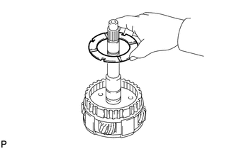
45.INSPECT OVERDRIVE PLANETARY GEAR ASSEMBLY
46.REMOVE OVERDRIVE PLANETARY RING GEAR WITH OVERDRIVE PLANETARY RING GEAR FLANGE
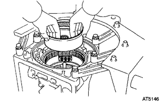
Remove the ring gear together with the overdrive planetary ring gear flange from the transmission case.
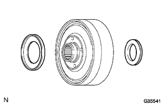
| *1 | Bearing |
| *2 | Bearing Race |
Remove the bearing and bearing race from the overdrive planetary ring gear.
47.REMOVE OVERDRIVE PLANETARY RING GEAR FLANGE
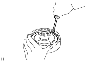
| *1 | Protective Tape |
Using a screwdriver, pry out the snap ring.
- NOTICE:
-
Be careful not to damage the overdrive planetary ring gear and the flange.
- HINT:
-
Tape the screwdriver tip before use.
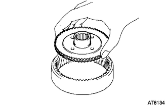
Remove the ring gear flange from the overdrive planetary ring gear.
48.REMOVE OVERDRIVE BRAKE DISC SET
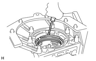
| *1 | Protective Tape |
Using a screwdriver, pry out the snap ring.
- NOTICE:
-
Be careful not to damage the transmission case.
- HINT:
-
Tape the screwdriver tip before use.
Remove the flange, 4 discs and 4 plates from the transmission case.
49.INSPECT OVERDRIVE BRAKE DISC
50.INSPECT PISTON STROKE OF SECOND COAST BRAKE
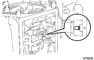
| *1 | Piston Rod |
| *2 | Mark |
Using a waterproof pen, place a mark on the second coast brake piston rod as shown in the illustration.
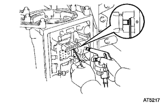
Using SST, measure the piston stroke while applying and releasing compressed air (392 kPa (4.0 kgf/cm2, 57 psi)).
- SST
- 09240-00020
- Standard piston stroke:
1.5 to 3.0 mm (0.0591 to 0.118 in.)
If the stroke is not as specified, inspect the brake band.
51.REMOVE OVERDRIVE SUPPORT SUB-ASSEMBLY
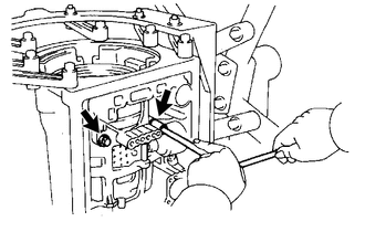
Remove the 2 bolts holding the overdrive support sub-assembly to the case.
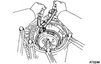
Using SST, remove the snap ring.
- SST
- 09350-30020 (09350-07060)
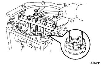
Using SST, remove the overdrive brake assembly.
- SST
- 09350-30020 (09350-07020)
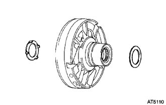
| *1 | Bearing |
| *2 | Bearing Race |
Remove the bearing and bearing race from the overdrive brake.
52.INSPECT PISTON OPERATION OF OVERDRIVE BRAKE
53.REMOVE DIRECT CLUTCH ASSEMBLY WITH FORWARD CLUTCH ASSEMBLY
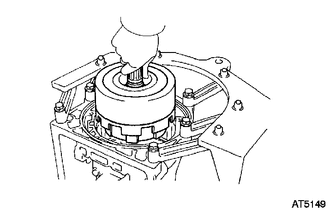
Remove the direct clutch together with the forward clutch from the case.
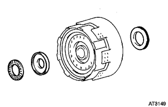
| *1 | Bearing |
| *2 | Bearing Race |
Remove the 2 bearings and bearing race.
54.REMOVE FORWARD CLUTCH ASSEMBLY
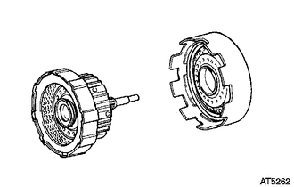
Remove the forward clutch from the direct clutch.
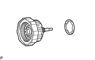
| *1 | Thrust Washer |
Remove the thrust washer from the forward clutch.
55.REMOVE OVERDRIVE BRAKE RETURN SPRING SUB-ASSEMBLY
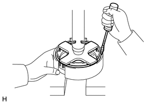
| *1 | Protective Tape |
Place SST on the return spring and compress the return spring with a press.
- SST
- 09350-30020 (09350-07030)
Using a screwdriver, pry out the snap ring.
- NOTICE:
-
Be careful not to damage the overdrive support sub-assembly and return spring.
- HINT:
-
Tape the screwdriver tip before use.
Remove the brake return spring.
56.INSPECT OVERDRIVE BRAKE RETURN SPRING SUB-ASSEMBLY
57.REMOVE OVERDRIVE BRAKE PISTON
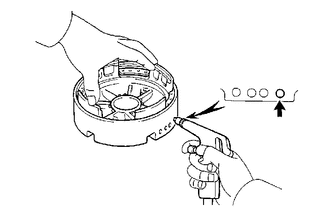
Place the overdrive support onto the direct clutch assembly.
Hold the overdrive brake piston so that it is not slanted and apply compressed air (392 kPa (4.0 kgf/cm2, 57 psi)) into the passage to remove the overdrive brake piston.
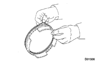
| *1 | O-Ring |
Remove the 2 O-rings from the overdrive brake piston.
58.REMOVE OVERDRIVE CLUTCH DRUM OIL SEAL RING
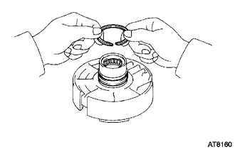
Remove the 2 oil seal rings from the overdrive support.
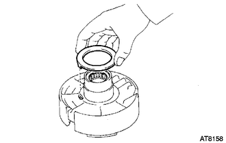
Remove the clutch drum thrust washer from the overdrive support.
59.REMOVE SECOND COAST BRAKE PISTON
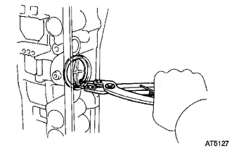
Using SST, remove the snap ring.
- SST
- 09350-30020 (09350-07060)
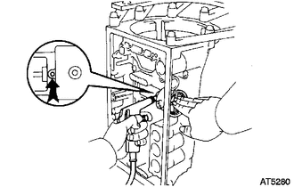
Apply compressed air to the oil hole to remove the second coast brake cover, piston assembly and spring.
Remove the 2 O-rings from the cover.
60.REMOVE SECOND COAST BRAKE PISTON OIL SEAL RING
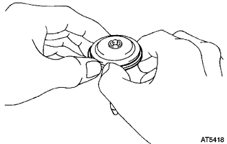
61.REMOVE SECOND COAST BRAKE PISTON ROD
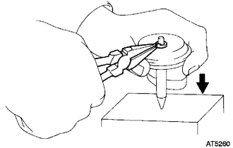
Firmly press the piston down to compress the compression spring.
Remove the E-ring.
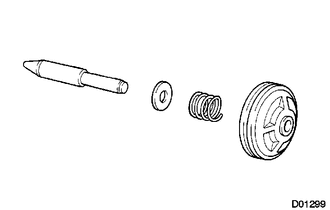
| *1 | Piston Rod |
| *2 | Washer Plate |
| *3 | Spring |
| *4 | Piston |
Remove the piston rod, washer plate and spring from the piston.
62.REMOVE DIRECT CLUTCH DISC SET
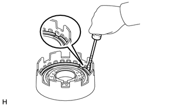
| *1 | Protective Tape |
Using a screwdriver, pry out the snap ring from the direct clutch drum.
- NOTICE:
-
Be careful not to damage the direct clutch drum.
- HINT:
-
Tape the screwdriver tip before use.
Remove the flange, 4 discs and 4 plates.
63.INSPECT DIRECT CLUTCH DISC
64.REMOVE DIRECT CLUTCH RETURN SPRING SUB-ASSEMBLY
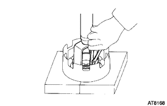
Place SST on the return spring and compress the return spring with a press.
- SST
- 09350-30020 (09350-07040)
Using SST, remove the snap ring.
- SST
- 09350-30020 (09350-07070)
Remove the return spring.
65.INSPECT DIRECT CLUTCH RETURN SPRING SUB-ASSEMBLY
66.REMOVE DIRECT CLUTCH PISTON SUB-ASSEMBLY
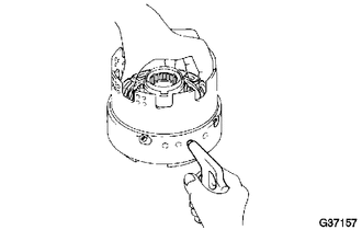
Place the direct clutch drum on the overdrive support.
Hold the direct clutch piston and apply compressed air (196 kPa (2.0 kgf/cm2, 28.5 psi)) to the overdrive support to remove the direct clutch piston.
- HINT:
-
Make sure the direct clutch piston is not tilted before applying compressed air.
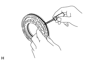
| *1 | O-Ring |
| *2 | Protective Tape |
Using a small screwdriver, remove the 2 O-rings from the piston.
- NOTICE:
-
Be careful not to damage the direct clutch piston sub-assembly.
- HINT:
-
Tape the screwdriver tip before use.
67.INSPECT DIRECT CLUTCH PISTON SUB-ASSEMBLY
68.INSPECT DIRECT CLUTCH DRUM SUB-ASSEMBLY
69.FIX FORWARD CLUTCH ASSEMBLY
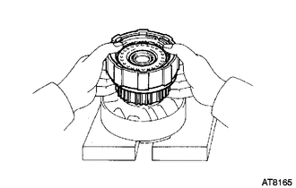
Place the overdrive support on wooden blocks or equivalent to prevent the forward clutch shaft from touching the work stand.
Place the forward clutch on the overdrive support.
70.REMOVE FORWARD CLUTCH DISC SET
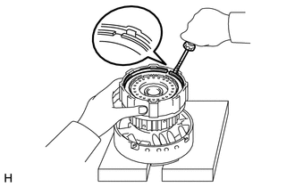
| *1 | Protective Tape |
Using a screwdriver, pry out the snap ring from the input shaft.
- NOTICE:
-
Be careful not to damage the input shaft.
- HINT:
-
Tape the screwdriver tip before use.
Remove the flange, 6 discs, 6 plates and cushion plate.
71.INSPECT FORWARD CLUTCH DISC
72.REMOVE FORWARD CLUTCH RETURN SPRING SUB-ASSEMBLY
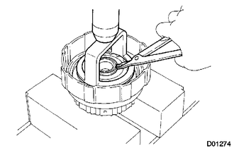
Place SST on the return spring and compress the return spring with a press.
- SST
- 09350-30020 (09350-07040)
Using SST, remove the snap ring.
- SST
- 09350-30020 (09350-07070)
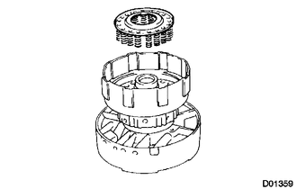
Remove the return spring.
73.INSPECT FORWARD CLUTCH RETURN SPRING SUB-ASSEMBLY
74.REMOVE FORWARD CLUTCH PISTON SUB-ASSEMBLY
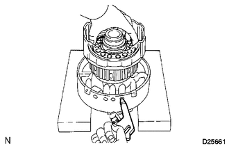
Place the input shaft onto the overdrive support.
Hold the forward clutch piston by hand and apply compressed air (196 kPa (2.0 kgf/cm2, 28.5 psi)) to the overdrive support to remove the forward clutch piston.
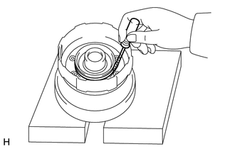
| *1 | Protective Tape |
Remove the O-ring from the input shaft.
- NOTICE:
-
Be careful not to damage the input shaft.
- HINT:
-
Tape the screwdriver tip before use.
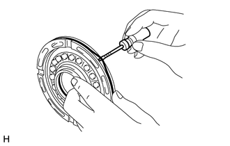
| *1 | O-Ring |
| *2 | Protective Tape |
Remove the 2 O-rings from the forward clutch piston.
- NOTICE:
-
Be careful not to damage the forward clutch piston sub-assembly.
- HINT:
-
Tape the screwdriver tip before use.
75.INSPECT FORWARD CLUTCH PISTON SUB-ASSEMBLY
76.REMOVE INPUT SHAFT OIL SEAL RING
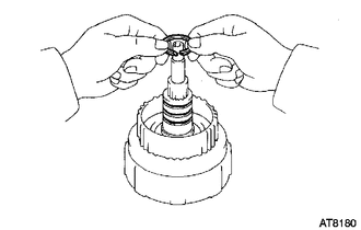
Remove the 3 oil seal rings from the grooves of the input shaft.
77.INSPECT INPUT SHAFT SUB-ASSEMBLY
78.REMOVE SECOND COAST BRAKE BAND ASSEMBLY
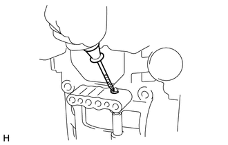
| *1 | Protective Tape |
Using a screwdriver, pry off the 2 E-rings from the pin and pull out the pin.
- NOTICE:
-
Be careful not to damage the transmission case.
- HINT:
-
Tape the screwdriver tip before use.
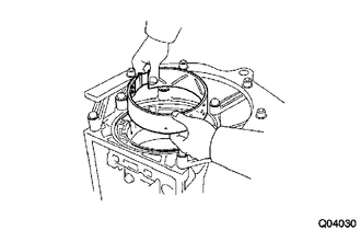
Remove the second coast brake band from the case.
79.INSPECT SECOND COAST BRAKE BAND ASSEMBLY
80.REMOVE FRONT PLANETARY RING GEAR SUB-ASSEMBLY
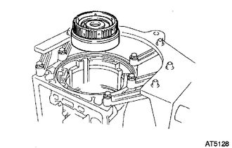
Remove the planetary ring gear from the case.
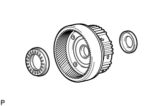
| *1 | Bearing |
| *2 | Bearing Race |
Remove the bearing and bearing race from the planetary ring gear.
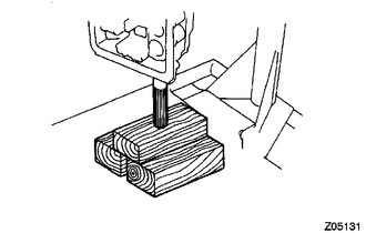
| *1 | Wooden Block |
Place the output shaft on wooden blocks or equivalent.
81.INSPECT FRONT PLANETARY RING GEAR SUB-ASSEMBLY
82.REMOVE FRONT PLANETARY GEAR ASSEMBLY
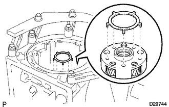
Remove the bearing race from the planetary gear.
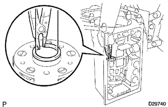
Using SST, remove the snap ring.
- SST
- 09350-30020 (09350-07070)
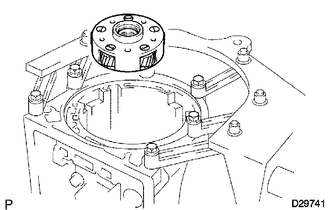
Remove the planetary gear from the case.
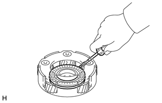
| *1 | Protective Tape |
Remove the bearing and bearing race from the planetary gear.
- NOTICE:
-
Be careful not to damage the planetary gear.
- HINT:
-
Tape the screwdriver tip before use.
83.INSPECT FRONT PLANETARY GEAR ASSEMBLY
84.REMOVE PLANETARY SUN GEAR SUB-ASSEMBLY WITH SUN GEAR INPUT DRUM AND NO. 1 1-WAY CLUTCH ASSEMBLY
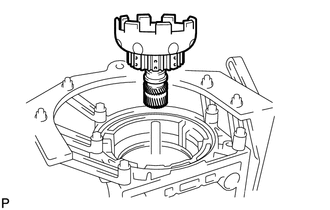
Remove the sun gear together with the sun gear input drum and 1-way clutch from the case.
85.INSPECT NO. 1 1-WAY CLUTCH ASSEMBLY
86.REMOVE NO. 1 1-WAY CLUTCH ASSEMBLY
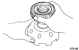
87.REMOVE NO. 1 1-WAY CLUTCH THRUST WASHER
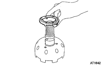
88.REMOVE SUN GEAR SHAFT OIL SEAL RING
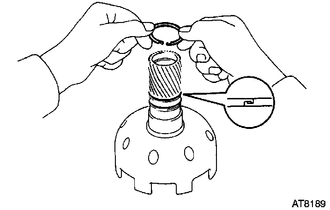
Remove the 2 oil seal rings from the sun gear input drum.
89.REMOVE SUN GEAR INPUT DRUM
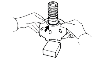
Place the planetary sun gear onto a wooden block or equivalent.
Using snap ring pliers, remove the snap ring.
Remove the input drum from the planetary sun gear.
90.REMOVE SUN GEAR INPUT DRUM SHAFT SNAP RING
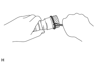
| *1 | Protective Tape |
Using a screwdriver, pry off the snap ring from the planetary sun gear.
- NOTICE:
-
Be careful not to damage the planetary sun gear.
- HINT:
-
Tape the screwdriver tip before use.
91.INSPECT PLANETARY SUN GEAR SUB-ASSEMBLY
92.REMOVE SECOND BRAKE DISC SET
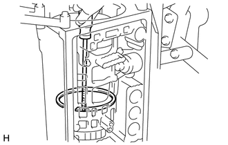
| *1 | Protective Tape |
Using a screwdriver, pry out the snap ring.
- NOTICE:
-
Be careful not to damage the transmission case.
- HINT:
-
Tape the screwdriver tip before use.
Remove the flange, 5 discs and 5 plates.
93.REMOVE SECOND BRAKE PISTON SLEEVE
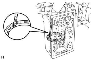
| *1 | Protective Tape |
Using a screwdriver, remove the sleeve.
- NOTICE:
-
Be careful not to damage the transmission case and sleeve.
- HINT:
-
Tape the screwdriver tip before use.
94.REMOVE OUTPUT SHAFT WITH REAR PLANETARY GEAR, NO. 2 1-WAY CLUTCH, FIRST AND REVERSE BRAKE DISC SET AND SECOND BRAKE DRUM
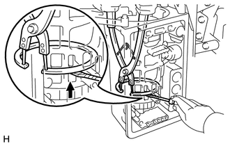
| *1 | Protective Tape |
Using SST and a screwdriver, remove the snap ring.
- SST
- 09350-30020 (09350-07060)
- NOTICE:
-
Be careful not to damage the transmission case.
- HINT:
-
Tape the screwdriver tip before use.
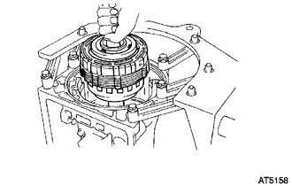
Remove the output shaft together with the rear planetary gear, No. 2 1-way clutch, first and reverse brake disc set and second brake drum from the transmission case.
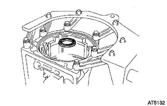
Remove the bearing from the transmission case.
95.REMOVE SECOND BRAKE DRUM SUB-ASSEMBLY
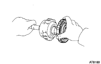
Remove the second brake drum.
96.REMOVE NO. 4 PLANETARY CARRIER THRUST WASHER
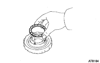
97.INSPECT SECOND BRAKE PISTON
98.REMOVE SECOND BRAKE PISTON RETURN SPRING SUB-ASSEMBLY
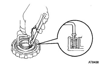
Place SST on the return spring and compress the piston return spring with a press.
- SST
- 09350-30020 (09350-07040)
- NOTICE:
-
Do not deform the spring seat. Stop compressing the spring when the spring seat is lowered to a position 1 to 2 mm (0.0394 to 0.0787 in.) from the snap ring groove.
Using SST, remove the snap ring.
- SST
- 09350-30020 (09350-07070)
Remove the second brake piston return spring seat.
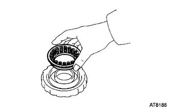
Remove the piston return spring.
99.INSPECT SECOND BRAKE PISTON RETURN SPRING SUB-ASSEMBLY
100.REMOVE SECOND BRAKE PISTON
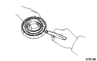
Hold the second brake piston by hand and apply compressed air to the second brake drum to remove the second brake piston.
- HINT:
-
If the piston is at an angle and cannot be removed, press down on the protruding side and apply compressed air again.
Remove the 2 O-rings from the piston.
101.REMOVE FIRST AND REVERSE BRAKE DISC SET
Remove the 7 plates, 7 discs and flange.
102.INSPECT FIRST AND REVERSE BRAKE DISC
103.REMOVE OUTPUT SHAFT
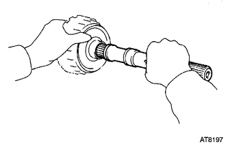
104.REMOVE PLANETARY OUTPUT SHAFT OIL SEAL RING
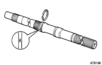
105.REMOVE REAR PLANETARY RING GEAR
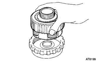
Remove the rear planetary gear from the planetary ring gear.
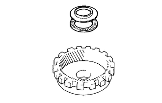
Remove the bearing race and bearing from the planetary ring gear.
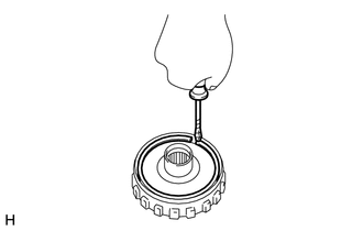
| *1 | Protective Tape |
Using a screwdriver, pry out the snap ring.
- NOTICE:
-
Be careful not to damage the rear planetary ring gear.
- HINT:
-
Tape the screwdriver tip before use.
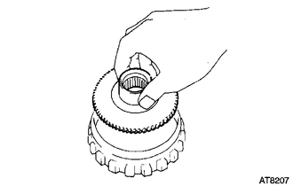
Remove the planetary ring gear flange.
106.INSPECT NO. 2 1-WAY CLUTCH
107.REMOVE NO. 2 1-WAY CLUTCH
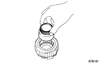
Remove the 1-way clutch inner race from the planetary gear.
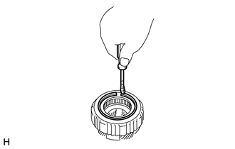
| *1 | Protective Tape |
Using a screwdriver, pry out the snap ring.
- NOTICE:
-
Be careful not to damage the rear planetary gear.
- HINT:
-
Tape the screwdriver tip before use.
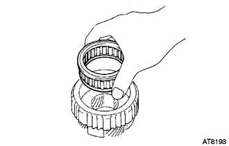
Remove the 1-way clutch from the planetary gear.
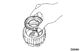
Remove the No. 2 planetary carrier thrust washer from the planetary gear.
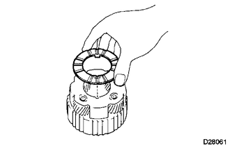
Remove the No. 1 planetary carrier thrust washer from the planetary gear.
108.INSPECT REAR PLANETARY GEAR ASSEMBLY
109.REMOVE LEAF SPRING
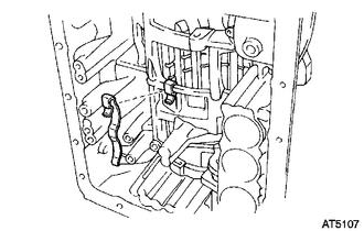
110.REMOVE BRAKE DRUM GASKET
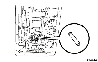
111.REMOVE FIRST AND REVERSE BRAKE RETURN SPRING SUB-ASSEMBLY
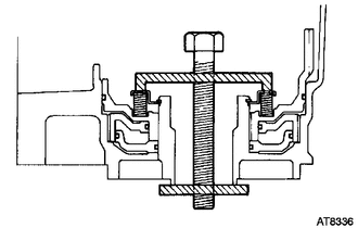
| *1 | Snap Ring |
Place SST on the first and reverse brake return spring and compress the brake return spring.
- SST
- 09350-30020 (09350-07050)
Using SST, remove the snap ring and brake return spring.
- SST
- 09350-30020 (09350-07070)
112.INSPECT 1ST AND REVERSE BRAKE RETURN SPRING SUB-ASSEMBLY
113.REMOVE NO. 2 FIRST AND REVERSE BRAKE PISTON
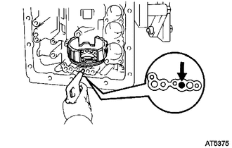
Hold the No. 2 first and reverse brake piston and apply compressed air to the transmission case to remove the brake piston.
- HINT:
-
If the piston does not pop out with compressed air, lift the piston out with needle-nose pliers.
Remove the O-ring from the brake piston.
114.REMOVE BRAKE REACTION SLEEVE
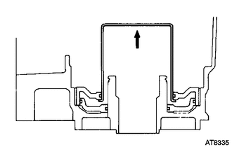
Using SST, remove the sleeve.
- SST
- 09350-30020 (09350-07080)
Remove the O-ring from the sleeve.
115.REMOVE NO. 1 1ST AND REVERSE BRAKE PISTON
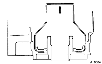
Using SST, remove the brake piston.
- SST
- 09350-30020 (09350-07090)
Remove the 2 O-rings from the brake piston.
116.INSPECT TRANSMISSION CASE BUSH