DRIVE SHAFT / PROPELLER SHAFT PROPELLER SHAFT ASSEMBLY(for TASA Made) INSTALLATION
PROCEDURE

 1.INSTALL PROPELLER SHAFT WITH CENTER BEARING ASSEMBLY (for Pre-Runner)
Remove SST from the extension housing.
Install the propeller shaft to the extension housing.
Temporarily install the center support bearing bracket with the 2 plates and 2 bolts. Tighten the bolts as much as possible by hand.
Completely remove any oil or the like and clean the contact surfaces of the propeller shaft flange and differential flange.
Align the matchmarks on the propeller shaft flange and differential flange.
Connect the propeller shaft with the 4 bolts, 4 washers and 4 nuts.
- Torque:
- 88 N*m (899 kgf*cm, 65 ft.*lbf)
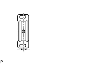
| *a | Center Bearing Housing Center Line |
| *b | Center Bearing Center Line |
Unload the vehicle. The center lines of the center bearing and center bearing housing (refer to the illustration) must be adjusted so that they are within 0 +/-1 mm (0 +/-0.0394 in.) of each other. Measure the difference along the front/rear axis of the vehicle.
- Distance (A):
0 +/-1 mm (0 +/-0.0394 in.)
Tighten the 2 bolts of the center support bearing bracket.
- Torque:
- 36 N*m (369 kgf*cm, 27 ft.*lbf)
2.INSTALL PROPELLER SHAFT WITH CENTER BEARING ASSEMBLY (for 4WD)
Completely remove any oil or the like and clean the contact surfaces of the propeller shaft flange and transfer flange.
Align the matchmarks on the propeller shaft flange and transfer flange.
Install the propeller shaft with the 4 nuts and 4 washers.
- Torque:
- 88 N*m (899 kgf*cm, 65 ft.*lbf)
Temporarily install the center support bearing bracket with the 2 plates and 2 bolts. Tighten the bolts as much as possible by hand.
Completely remove any oil or the like and clean the contact surfaces of the propeller shaft flange and differential flange.
Align the matchmarks on the propeller shaft flange and differential flange.
Connect the propeller shaft with the 4 bolts, 4 washers and 4 nuts.
- Torque:
- 88 N*m (899 kgf*cm, 65 ft.*lbf)
| *a | Center Bearing Housing Center Line |
| *b | Center Bearing Center Line |
Unload the vehicle. The center lines of the center bearing and center bearing housing (refer to the illustration) must be adjusted so that they are within 0 +/-1 mm (0 +/-0.0394 in.) of each other. Measure the difference along the front/rear axis of the vehicle.
- Distance (A):
0 +/-1 mm (0 +/-0.0394 in.)
Tighten the 2 bolts of the center support bearing bracket.
- Torque:
- 36 N*m (369 kgf*cm, 27 ft.*lbf)