AXLE AND DIFFERENTIAL REAR AXLE SHAFT REASSEMBLY
PROCEDURE

 1.INSTALL REAR AXLE SHAFT BEARING LH
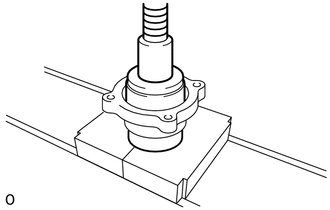
Using SST and a press, press in a new bearing.
- SST
- 09515-21010
09950-60020 (09951-00810)
2.INSTALL REAR AXLE SHAFT OUTER OIL SEAL
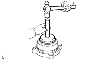
Using SST and a hammer, tap in a new oil seal.
- SST
- 09950-60020 (09951-00680)
09950-70010 (09951-07150)
3.INSTALL REAR AXLE HUB BOLT LH
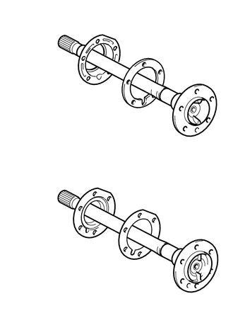
| *A | for 2WD |
| *B | for 4WD and Pre-Runner |
| *1 | Oil Drain Hole |
Install a new gasket and the deflector to the axle shaft.
- HINT:
-
Align the 3 oil drain holes.
for 2WD:
Pass 5 new hub bolts through the axle hub.
for 4WD and Pre-Runner:
Pass 6 new hub bolts through the axle hub.
Secure the axle shaft between aluminum plates in a vise.
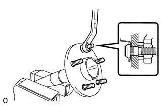
for 2WD:
Temporarily install a washer and nut to each of the 5 hub bolts as shown in the illustration.
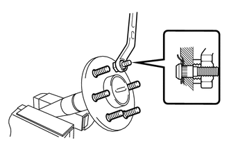
for 4WD and Pre-Runner:
Temporarily install a washer and nut to each of the 6 hub bolts as shown in the illustration.
Install the hub bolts by tightening each nut.
Remove the washer and nut from each hub bolt.
4.INSTALL BACKING PLATE TO REAR AXLE HOUSING SETTING BOLT
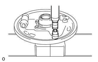
Position the backing plate on the bearing case.
Using 2 socket wrenches and a press, press in 4 new setting bolts.
5.INSTALL REAR AXLE BEARING INNER RETAINER LH (w/o ABS)
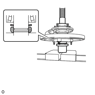
| *1 | Tapered Surface |
| *2 | Chamfered Surface |
Heat a new retainer to approximately 70 to 130°C (158 to 266°F).
Install a new shaft washer and the retainer to the axle shaft as shown in the illustration.
- NOTICE:
- ·
Install the shaft washer with its tapered surface facing downward.
·Install the retainer with its chamfered surface facing downward.
Using SST and a press, press in the axle shaft.
- SST
- 09951-01100
09631-12090
09726-40010
Using a snap ring expander, install a new snap ring.
6.INSTALL REAR AXLE BEARING INNER RETAINER LH AND REAR SKID CONTROL ROTOR (w/ ABS)
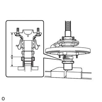
Using SST and a press, press in a new skid control rotor and a new retainer to the axle shaft until the lengths are as specified.
- SST
- 09951-01100
09631-12090
09726-40010
- Standard Length:
Length A Length B 133.2 +/-0.6 mm (5.244 +/-0.0236 in.) 56 mm (2.205 in.)
- NOTICE:
-
If this installation measurement is not followed precisely, oil leaks and other mechanical failures will result. Follow the assembly instructions closely, and confirm that parts have been installed so that the lengths are as specified.
- HINT:
-
It may be easier to verify that the lengths are as specified by adding the length of SST to the standard length, and then measuring the height from the surface of the press.