RM1840EF
_54
Brake
_009623
BRAKE CONTROL / DYNAMIC CONTROL SYSTEMS
_0052600
ANTI-LOCK BRAKE SYSTEM
U
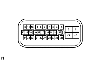
BRAKE CONTROL / DYNAMIC CONTROL SYSTEMS ANTI-LOCK BRAKE SYSTEM TERMINALS OF ECU
TERMINAL OF ECU
0.167,0.083 0.542,0.396
0.375,0.313
10
*a
| *a | Component without harness connected
(Skid Control ECU [Brake Actuator Assembly]) |
| Terminal No. (Symbol) | Terminal Description |
|---|---|
| 1 (+BS) | ABS solenoid power supply |
| 2 (GND1) | Ground |
| 3 (EXI4)* | L4 position switch (No. 1 transfer indicator switch) input |
| 4 (GL1) | Deceleration sensor signal input |
| 7 (GGND) | Deceleration sensor ground |
| 8 (FL-) | Front LH wheel speed signal input |
| 9 (FL+) | Front LH wheel speed signal input |
| 10 (STP) | Stop light switch input |
| 11 (RL+) | Rear LH wheel speed signal input |
| 12 (RL-) | Rear LH wheel speed signal input |
| 13 (WA) | ABS warning light output |
| 14 (D/G) | Diagnosis tester communication line |
| 15 (TS) | Signal check input |
| 16 (TC) | Diagnosis input |
| 17 (EXI)* | 4WD detection switch (Differential vacuum actuator assembly) input |
| 18 (PKB) | Parking brake switch input |
| 22 (EXI2) | IG power supply input |
| 23 (+BM) | ABS motor relay power supply |
| 24 (GND2) | Ground |
| 25 (IG1) | Skid control ECU (Brake actuator assembly) power supply |
| 28 (VGS) | Deceleration sensor power supply |
| 30 (FR-) | Front RH wheel speed signal input |
| 31 (FR+) | Front RH wheel speed signal input |
| 33 (RR+) | Rear RH wheel speed signal input |
| 34 (RR-) | Rear RH wheel speed signal input |
*: for 4WD
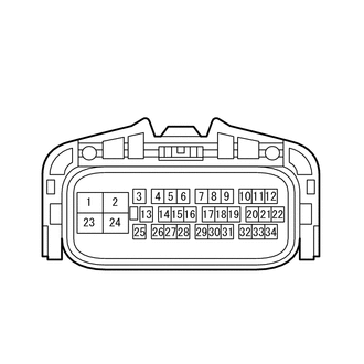
TERMINAL INSPECTION
1.479,0.698 1.896,0.948
0.417,0.25
0.115,0.156 0.49,0.427
0.375,0.271
10
*a
1.573,0.74 2.115,1.125
0.542,0.385
10
A13
| *a | Front view of wire harness connector
(to Skid Control ECU [Brake Actuator Assembly]) |
a.
Disconnect the skid control ECU (brake actuator assembly) connector.
b.
Measure the voltage and resistance according to the value(s) in the table below.
| Terminal No. (Symbol) | Wiring Color | Terminal Description | Condition | Specified Condition |
|---|---|---|---|---|
| A13-1 (+BS) - Body ground | W-R | ABS solenoid power supply | Always | 11 to 14 V |
| A13-2 (GND1) - Body ground | W-B | Ground | Always | Below 1 Ω |
| A13-3 (EXI4)* - Body ground | G-W | L4 position switch (No. 1 transfer indicator switch) input | Transfer shift position L4 | Below 1 Ω |
| A13-10 (STP) - Body ground | G-W | Stop light switch input | Brake pedal depressed | 8 to 14 V |
| Brake pedal released | Below 1.5 V | |||
| A13-17 (EXI)* - Body ground | R-B | 4WD detection switch (Differential vacuum actuator assembly) input | ·
Ignition switch ON ·
Transfer shift position H2 |
11 to 14 V |
| A13-18 (PKB) - Body ground | L-O | Parking brake switch input | ·
Ignition switch ON ·
Parking brake applied |
Below 1.5 V |
·
Ignition switch ON ·
Parking brake released |
10 to 14 V | |||
| A13-22 (EXI2) - Body ground | V | IG power supply input | Ignition switch ON | 11 to 14 V |
| A13-23 (+BM) - Body ground | R | ABS motor relay power supply | Always | 11 to 14 V |
| A13-24 (GND2) - Body ground | W-B | Ground | Always | Below 1 Ω |
| A13-25 (IG1) - Body ground | B | Skid control ECU (Brake actuator assembly) power supply | Ignition switch ON | 11 to 14 V |
*: for 4WD
If the result is not as specified, there may be a malfunction on the wire harness side.