STEERING GEAR / LINKAGE STEERING GEAR REMOVAL
CAUTION / NOTICE / HINT
PROCEDURE

 1.REMOVE FRONT WHEELS
2.REMOVE NO. 2 ENGINE UNDER COVER
Remove the 4 bolts and under cover.
3.REMOVE NO. 1 ENGINE UNDER COVER
Remove the 4 bolts and under cover.
4.REMOVE FRONT SIDE MEMBER TO FRONT SUSPENSION CROSSMEMBER BRACE
Remove the 10 bolts and 2 crossmember braces.
5.REMOVE FRONT STABILIZER BAR
6.DISCONNECT TIE ROD END SUB-ASSEMBLY LH
Remove the cotter pin and nut.
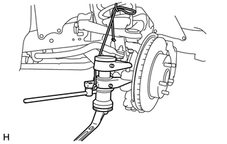
Using SST, disconnect the tie rod end from the steering knuckle arm.
- SST
- 09628-00011
7.DISCONNECT TIE ROD END SUB-ASSEMBLY RH
- HINT:
-
Use the same procedure described for the LH side.
8.DISCONNECT STEERING SLIDING YOKE
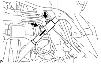
| *1 | Matchmark |
Loosen the bolt labeled A.
Place matchmarks on the steering sliding yoke and steering intermediate shaft.
Remove the bolt labeled B.
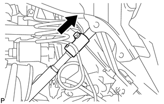
Disconnect the steering sliding yoke from the steering intermediate shaft.
9.REMOVE NO. 2 STEERING INTERMEDIATE SHAFT SUB-ASSEMBLY
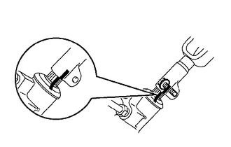
| *1 | Matchmark |
Place matchmarks on the intermediate shaft and steering link.
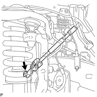
Remove the bolt.
Remove the intermediate shaft from the steering link.
10.DISCONNECT PRESSURE FEED TUBE ASSEMBLY
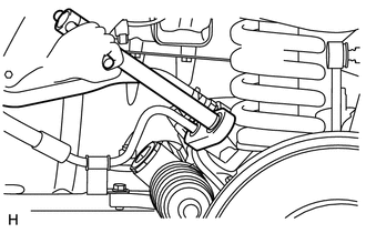
| *1 | Union Nut Wrench |
Using a union nut wrench, loosen the flare nut and disconnect the pressure feed tube.
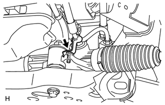
Remove the bolt and disconnect the pressure feed tube from the steering link.
11.DISCONNECT STEERING GEAR OUTLET RETURN TUBE
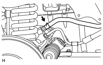
Detach the clip and disconnect the return hose.
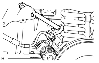
| *1 | Union Nut Wrench |
Using a union nut wrench, disconnect the outlet return tube.
12.REMOVE POWER STEERING LINK ASSEMBLY
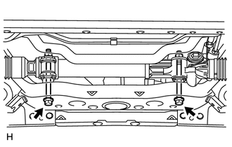
Fix the 2 nuts in place and remove the 2 bolts. Then remove the link from the frame.
- NOTICE:
-
Never turn the nut. Be sure to turn the bolt.
- HINT:
-
Removal of the link may be easier if the following is performed: 1) remove the differential mount, and 2) slide the differential toward the rear of the vehicle.