STEERING GEAR / LINKAGE STEERING GEAR DISASSEMBLY
CAUTION / NOTICE / HINT
- NOTICE:
- ·
When using a vise, place aluminum plates between the part and vise.
·When using a vise, do not overtighten it.
- HINT:
- ·
Use the same procedure for RHD and LHD vehicles.
·The procedure listed below is for LHD vehicles.
PROCEDURE

 1.REMOVE STEERING TURN PRESSURE TUBE
Using a union nut wrench, remove the 2 turn pressure tubes.
Remove the 4 O-rings.
2.SECURE POWER STEERING LINK ASSEMBLY
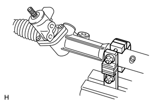
Using SST, secure the steering link between aluminum plates in a vise, as shown in the illustration.
- SST
- 09612-00012
3.REMOVE TIE ROD END SUB-ASSEMBLY LH
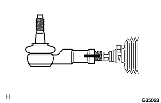
| *1 | Matchmark |
Place matchmarks on the tie rod end, lock nut and rack end.
Loosen the lock nut and remove the tie rod end and lock nut.
4.REMOVE TIE ROD END SUB-ASSEMBLY RH
- HINT:
-
Use the same procedure described for the LH side.
5.REMOVE STEERING RACK BOOT CLAMP LH
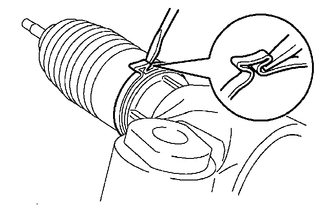
Using pliers and a screwdriver, remove the clamp.
- NOTICE:
-
Be careful not to damage the boot.
6.REMOVE STEERING RACK BOOT CLAMP RH
- HINT:
-
Use the same procedure described for the LH side.
7.REMOVE STEERING RACK BOOT CLIP LH
Using pliers, remove the clip.
- NOTICE:
-
Be careful not to damage the boot.
8.REMOVE STEERING RACK BOOT CLIP RH
- HINT:
-
Use the same procedure described for the LH side.
9.REMOVE STEERING RACK BOOT LH
10.REMOVE STEERING RACK BOOT RH
11.REMOVE STEERING RACK END SUB-ASSEMBLY
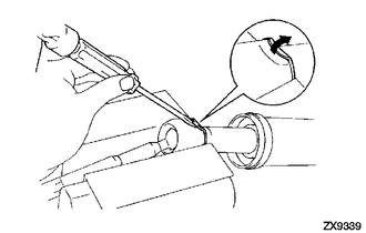
Using a screwdriver and hammer, unstake the washers.
- NOTICE:
-
Do not strike the steering rack.
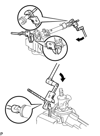
| *A | for RH Side |
| *B | for LH Side |
| *1 | Wrench |
| *a | Hold |
| *b | Turn |
Using a wrench, hold the steering rack (LH side).
Using SST, remove the steering rack end (LH side) from the power steering rack.
- SST
- 09922-10010
- HINT:
-
Rotate SST in the direction shown in the illustration.
Using SST, remove the steering rack end (RH side) from the power steering rack.
- SST
- 09922-10010
- HINT:
-
Rotate SST in the direction shown in the illustration.
Remove the 2 claw washers.
12.REMOVE RACK GUIDE
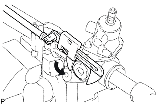
Using SST, remove the lock nut.
- SST
- 09922-10010
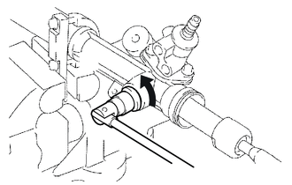
| *1 | 12 mm Socket Wrench |
Using a 12 mm socket wrench, remove the rack guide spring cap.
Remove the spring and rack guide.
13.REMOVE POWER STEERING CONTROL VALVE
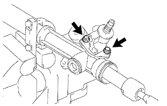
Remove the 2 bolts.
Pull out the control valve from the rack housing.
Remove the control valve gasket.
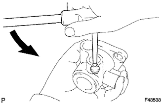
| *1 | Screw Extractor |
Using a screw extractor, remove the 2 union seats from the control valve housing.
14.REMOVE CYLINDER END STOPPER
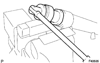
Using SST, remove the stopper.
- SST
- 09631-20120
15.REMOVE POWER STEERING RACK AND OIL SEAL
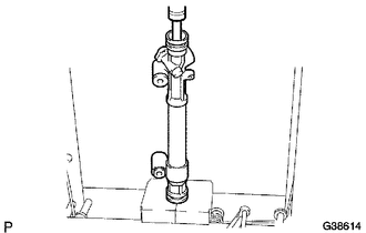
Using SST, press out the steering rack and oil seal.
- SST
- 09950-70010 (09951-07200)
- NOTICE:
-
Take care not to drop the steering rack.
Remove the oil seal from the steering rack.
Remove the bush from the steering rack.
16.INSPECT POWER STEERING RACK
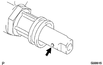
Insert a wire 20 mm (0.787 in.) into the vent hole of the steering rack and make sure that the vent hole is not clogged with grease.
- NOTICE:
-
If the hole is clogged, the pressure inside the boot will change after the boot is assembled and the steering wheel is turned.
17.REMOVE "TEFLON" RING
Using a screwdriver, remove the "Teflon" ring and O-ring from the steering rack.
- NOTICE:
-
Be careful not to damage the groove of the ring.
18.REMOVE POWER STEERING CYLINDER TUBE OIL SEAL
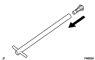
Install SST (09612-07120) to SST (09612-07210).
- SST
- 09612-70100 (09612-07120, 09612-07210)
- NOTICE:
- ·
Lightly apply MP grease to the tip of SST (09612-07230) and inside of SST (09612-07210 and 09612-07120) before use.
·Completely install SST (09612-07120) to SST (09612-07210) to prevent damage to the inside of the rack housing.
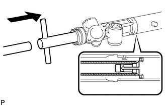
Insert SST (09612-07210) into the rack housing at an angle until it comes in contact with the power steering cylinder tube oil seal. Install SST (09612-07220) to SST (09612-07210).
- SST
- 09612-70100 (09612-07120, 09612-07210, 09612-07220)
- NOTICE:
-
Do not damage the inside of the power steering rack housing.
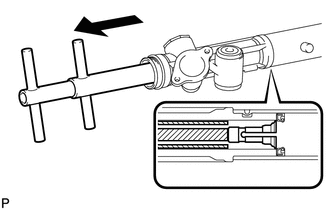
Hold SST (09612-07220) and pull SST (09612-07210) to position SST (09612-07120) inside of the rack housing.
- SST
- 09612-70100 (09612-07120, 09612-07210, 09612-07220, 09612-07230)
- HINT:
-
Make sure that SST (09612-07120) is positioned at the chamfered part between the power steering cylinder tube oil seal and the rack housing.
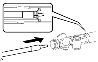
Install SST (09612-07240) to SST (09612-07230). Insert the tip of SST (09612-07230) into the service hole of SST (09612-07120) in the rack housing.
- SST
- 09612-70100 (09612-07120, 09612-07230, 09612-07240)
- NOTICE:
- ·
Make sure that SST (09612-07240) is installed to prevent damage to SST (09612-07120).
·Do not damage the inside of the rack housing.
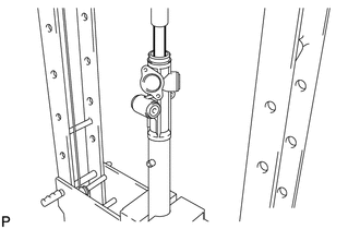
Install SST (09951-07150) to SST (09612-07230). Using a press, remove the power steering cylinder tube oil seal.
- SST
- 09612-70100 (09612-07120, 09612-07230, 09612-07240)
09950-70010 (09951-07150)
- NOTICE:
-
Do not damage the rack housing.
- HINT:
-
Replace SST (09951-07150) with another of different length from the set if necessary.