RM1840EF
_56
Audio / Visual / Telematics
_009632
NAVIGATION / MULTI INFO DISPLAY
_0052660
NAVIGATION ANTENNA
G
NAVIGATION / MULTI INFO DISPLAY NAVIGATION ANTENNA INSPECTION
PROCEDURE

 1.INSPECT NAVIGATION ANTENNA ASSEMBLY
a.
Temporarily replace the navigation antenna assembly with a new or normally functioning one.
- OK:
Malfunction disappears.
If the result is not as specified, replace the navigation antenna assembly.
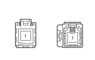
2.INSPECT NO. 1 NAVIGATION ANTENNA CORD SUB-ASSEMBLY
a.
0.875,1.313 0.323,1.313
false
1.115,1.313 1.417,1.313
false
2.552,1.333 1.938,1.333
false
2.823,1.354 3.115,1.354
false
0.063,0.042 0.333,0.26
0.271,0.219
10
*a
0.885,0.396 1.104,0.615
0.219,0.219
10
A
2.531,0.365 2.688,0.531
0.156,0.167
10
B
0.135,1.229 0.375,1.417
0.24,0.188
10
*1
1.438,1.219 1.667,1.417
0.229,0.198
10
*2
1.76,1.25 1.99,1.417
0.229,0.167
10
*1
3.135,1.26 3.354,1.438
0.219,0.177
10
*2
| *1 | Core wire |
| *2 | Shield |
| *a | Component without harness connected
(No. 1 navigation antenna cord sub-assembly) |
Measure the resistance according to the value(s) in the table below.
- Standard Resistance:
Tester Connection Condition Specified Condition A (Core wire) - B (Core wire) Always Below 1 Ω A (Shield) - B (Shield) Always Below 1 Ω A (Core wire) - A (Shield) or B (Core wire) - B (Shield) Always 10 kΩ or higher
If the result is not as specified, replace the No. 1 navigation antenna cord sub-assembly.