RM1840EF
_58
Vehicle Interior
_009648
HEATING / AIR CONDITIONING
_0052758
AIR CONDITIONING PRESSURE SENSOR
G
HEATING / AIR CONDITIONING AIR CONDITIONING PRESSURE SENSOR ON-VEHICLE INSPECTION
PROCEDURE

 1.INSPECT AIR CONDITIONING TUBE AND ACCESSORY ASSEMBLY
1.417,1.271 1.042,0.844
true
1.75,1.26 2.135,0.875
true
0.885,0.688 1.083,0.865
0.198,0.177
10
false
1
2.208,0.698 2.427,0.917
0.219,0.219
10
false
2
0.5,3.448 1.042,3.615
0.542,0.167
10
false
196 kPa
2.125,3.448 2.792,3.604
0.667,0.156
10
false
3140 kPa
0.125,0.167 0.333,0.354
0.208,0.188
10
false
*a
0.698,2.656 0.906,2.844
0.208,0.188
10
false
*b
1.542,2.656 1.719,2.833
0.177,0.177
10
false
*c
2.438,2.646 2.615,2.844
0.177,0.198
10
false
*d
0.656,3.833 0.865,3.99
0.208,0.156
10
false
*e
2.354,3.865 2.521,4.021
0.167,0.156
10
false
*e
0.083,3.615 1.521,3.844
1.438,0.229
10
false
(2.0 kgf/cm2, 28 psi)
1.667,3.635 3.24,3.865
1.573,0.229
10
false
(32.0 kgf/cm2, 455 psi)
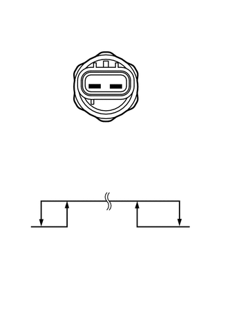
| *a | Component without harness connected
(Air Conditioning Pressure Sensor) |
| *b | Low Pressure Side |
| *c | On (Below 1.0 Ω) |
| *d | High Pressure Side |
| *e | Off (10 kΩ or higher) |
a.
Install a manifold gauge set.
b.
Connect the positive (+) lead from an ohmmeter to terminal 1 and the negative (-) lead to terminal 2.
c.
Check the resistance between terminals when refrigerant pressure is charged as shown in the illustration.
If the operation is not as specified, replace the air conditioning tube and accessory assembly (air conditioning pressure sensor).