Home › Vehicle Interior › HEATING / AIR CONDITIONING › AIR CONDITIONING SYSTEM(for Automatic Air Conditioning System) › 2011.10–2012.04
RM1840EF _58 Vehicle Interior _009648 HEATING / AIR CONDITIONING _0052762 AIR CONDITIONING SYSTEM(for Automatic Air Conditioning System) J

HEATING / AIR CONDITIONING  AIR CONDITIONING SYSTEM(for Automatic Air Conditioning System)  Blower Motor Circuit  


DESCRIPTION
E272299
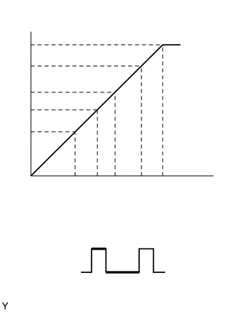
0.104,0.115 1.938,0.313 1.833,0.198 10 false Blower Level 0.229,0.594 0.458,0.792 0.229,0.198 10 false HI 0.188,0.917 0.417,1.115 0.229,0.198 10 false M3 0.188,1.281 0.417,1.479 0.229,0.198 10 false M2 0.177,1.542 0.406,1.74 0.229,0.198 10 false M1 0.219,1.875 0.448,2.073 0.229,0.198 10 false LO 0.354,2.635 0.583,2.833 0.229,0.198 10 false 0 1.021,2.635 1.333,2.833 0.313,0.198 10 false 24.9 1.354,2.635 1.667,2.833 0.313,0.198 10 false 38.9 1.667,2.635 2,2.833 0.333,0.198 10 false 53.0 2.021,2.635 2.385,2.854 0.365,0.219 10 false 69.4 2.354,2.635 2.688,2.833 0.333,0.198 10 false 100 1.417,2.927 2.292,3.188 0.875,0.26 10 false SI Duty (%) 0.729,3.177 2.917,3.438 2.188,0.26 10 false Duty Ratio (%) = A / (A + B) x 100 1.604,4.125 2.156,4.365 0.552,0.24 10 false 1 cycle 0.885,3.625 1.635,3.875 0.75,0.25 10 false Off 0.875,3.969 1.625,4.219 0.75,0.25 10 false On 1.406,3.49 1.583,3.677 0.177,0.188 10 false B 1.75,3.823 1.927,4.01 0.177,0.188 10 false A

The blower with fan motor sub-assembly is operated by signals from the air conditioning amplifier. Blower with fan motor sub-assembly speed signals are determined by changes in the duty ratio*.

The blower motor control controls the blower with fan motor sub-assembly speed. The blower motor control reads the signal from the air conditioning amplifier assembly and controls rotation and speed.

HINT:

*: The duty ratio is the ratio of the blower with fan motor sub-assembly on time (A) to the total of the blower with fan motor sub-assembly on and off time (A + B).


WIRING DIAGRAM
E225334
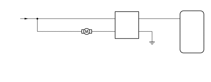
5.896,1.969 7.094,2.385 1.198,0.417 10 false Air Conditioning Amplifier Assembly 6.146,0.563 6.521,0.75 0.375,0.188 10 false BLW 5.896,1.802 6.229,1.969 0.333,0.167 10 false G94 3.865,1.333 4.167,1.49 0.302,0.156 10 false G78 5.969,0.448 6.094,0.604 0.125,0.156 10 false 2 4.76,0.438 4.885,0.594 0.125,0.156 10 false 3 4.76,0.885 4.885,1.042 0.125,0.156 10 false 4 3.76,0.885 3.885,1.042 0.125,0.156 10 false 1 3.167,0.896 3.292,1.052 0.125,0.156 10 false 1 3.76,0.438 3.885,0.594 0.125,0.156 10 false 2 2.656,0.896 2.781,1.052 0.125,0.156 10 false 2 2.375,1.188 2.833,1.344 0.458,0.156 10 false G15 3.948,1 4.219,1.177 0.271,0.177 10 false VM 4.531,0.552 4.74,0.698 0.208,0.146 10 false SI 3.938,0.552 4.188,0.76 0.25,0.208 10 false +B 4.396,1 4.76,1.188 0.365,0.188 10 false GND 3.875,1.479 4.719,1.833 0.844,0.354 10 false Blower Motor Control 2.375,1.385 3.656,1.948 1.281,0.563 10 false Blower with Fan Motor Sub-assembly 0.188,0.406 0.615,1.219 0.427,0.813 10 false from No. 1 Heater Relay

CAUTION / NOTICE / HINT

NOTICE:

Inspect the relays for circuits related to this system before performing the following inspection procedure.


PROCEDURE
1.INSPECT BLOWER WITH FAN MOTOR SUB-ASSEMBLY
a.
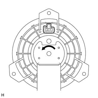
E218806

Remove the blower with fan motor sub-assembly.

Click hereVehicle Interior>HEATING / AIR CONDITIONING>FRONT BLOWER MOTOR>REMOVAL


b.

Apply battery voltage to the blower with fan motor sub-assembly and check the operation of the blower motor.

OK:
Measurement Condition Specified Condition
Battery positive (+) → Terminal 2
Battery negative (-) → Terminal 1
The blower motor operates smoothly


Result:
Proceed to
OK
NG


OK

2.CHECK HARNESS AND CONNECTOR (BLOWER MOTOR CONTROL - AIR CONDITIONING AMPLIFIER AND BODY GROUND)

NG

REPLACE BLOWER WITH FAN MOTOR SUB-ASSEMBLY

2.CHECK HARNESS AND CONNECTOR (BLOWER MOTOR CONTROL - AIR CONDITIONING AMPLIFIER AND BODY GROUND)
a.

Disconnect the G78 blower motor control connector.


b.

Disconnect the G94 air conditioning amplifier assembly connector.


c.

Measure the resistance according to the value(s) in the table below.

Standard Resistance:
Tester Connection Condition Specified Condition
G78-3 (SI) - G94-2 (BLW) Always Below 1 Ω
G78-4 (GND) - Body ground
G78-3 (SI) - Body ground Always 10 kΩ or higher
G78-2 (+B) - Body ground
G78-1 (VM) - Body ground


Result:
Proceed to
OK
NG


OK

3.CHECK HARNESS AND CONNECTOR (BLOWER MOTOR CONTROL - BLOWER WITH FAN MOTOR AND BATTERY)

NG

REPAIR OR REPLACE HARNESS OR CONNECTOR

3.CHECK HARNESS AND CONNECTOR (BLOWER MOTOR CONTROL - BLOWER WITH FAN MOTOR AND BATTERY)
a.

Disconnect the G78 blower motor control connector.


b.

Disconnect the G15 blower with fan motor sub-assembly connector.


c.

Measure the voltage according to the value(s) in the table below.

Standard Voltage:
Tester Connection Switch Condition Specified Condition
G78-2 (+B) - Body ground
·

Ignition switch ON

·

Blower switch on (LO level)


11 to 14 V
·

Ignition switch ON

·

Blower switch off


Below 1 V
G15-2 - Body ground
·

Ignition switch ON

·

Blower switch on (LO level)


11 to 14 V
·

Ignition switch ON

·

Blower switch off


Below 1 V


d.

Measure the resistance according to the value(s) in the table below.

Standard Resistance:
Tester Connection Condition Specified Condition
G15-1 - Body ground Always 10 kΩ or higher
G15-2 - Body ground
G78-1 (VM) - G15-1 Always Below 1 Ω


Result:
Proceed to
OK
NG


OK

4.CHECK AIR CONDITIONING AMPLIFIER ASSEMBLY

NG

REPAIR OR REPLACE HARNESS OR CONNECTOR

4.CHECK AIR CONDITIONING AMPLIFIER ASSEMBLY
a.
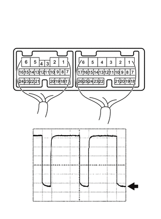
E272515
0.729,0.542 1.115,0.833 0.385,0.292 1.177,1.26 1.594,0.844 true 1.656,0.75 2.115,0.948 0.458,0.198 10 false BLW 0.802,0.604 1.156,0.802 0.354,0.198 10 false G94 0.094,0.083 0.448,0.281 0.354,0.198 10 false *a 2.74,2.615 3.333,2.823 0.594,0.208 10 false 1 V/DIV. 3,3.896 3.375,4.146 0.375,0.25 10 false GND 1.302,4.354 2.188,4.563 0.885,0.208 10 false 50 μsec./DIV.
*a Component with harness connected
(Air Conditioning Amplifier Assembly)


Remove the air conditioning amplifier assembly with its connectors still connected.

Click hereVehicle Interior>HEATING / AIR CONDITIONING>AIR CONDITIONING AMPLIFIER(for Automatic Air Conditioning System)>REMOVAL


b.

Using an oscilloscope, check the waveform of the amplifier.

Measurement Condition:
Item Content
Tester Connection G94-2 (BLW) - Body ground
Tool Setting 1 V/DIV., 50 μsec./DIV.
Condition Ignition switch ON, Blower switch on (LO level)


OK:

Waveform is as shown in the illustration.


HINT:

Waveform varies depending on the blower switch setting.


Result:
Proceed to
OK
NG


OK

NG