Home › Vehicle Exterior › WINDOW / GLASS › POWER WINDOW CONTROL SYSTEM(w/ Jam Protection Function) › 2011.10–2012.04
RM1840EF _59 Vehicle Exterior _009651 WINDOW / GLASS _0052778 POWER WINDOW CONTROL SYSTEM(w/ Jam Protection Function) J

WINDOW / GLASS  POWER WINDOW CONTROL SYSTEM(w/ Jam Protection Function)  Remote Up / Down Function does not Operate  


DESCRIPTION

With the ignition switch ON, the power window regulator master switch assembly transmits remote switch signals to the power window regulator switches of the front passenger side power window and rear power windows. Then, each power window regulator switch drives its respective power window regulator motor.

WIRING DIAGRAM
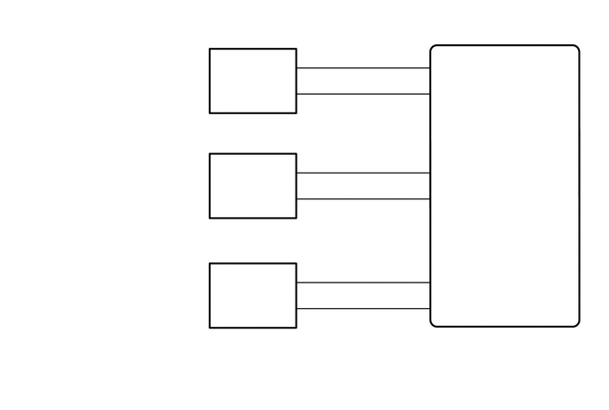
B295216
5.125,0.719 5.667,0.917 0.542,0.198 10 false U 5.125,4.083 6.688,4.573 1.563,0.49 10 false Power Window Regulator Master Switch Assembly 0.406,0.656 2.313,1.219 1.906,0.563 10 false Front Power Window Regulator Switch Assembly RH 0.396,1.927 2.281,2.594 1.885,0.667 10 false Rear Power Window Regulator Switch Assembly LH 0.406,3.208 2.292,3.75 1.885,0.542 10 false Rear Power Window Regulator Switch Assembly RH 5.135,1.052 5.698,1.219 0.563,0.167 10 false D 5.135,1.958 5.677,2.156 0.542,0.198 10 false U 5.135,2.271 5.677,2.469 0.542,0.198 10 false D 5.135,3.219 5.677,3.417 0.542,0.198 10 false U 5.135,3.552 5.677,3.75 0.542,0.198 10 false D 0.406,0.5 0.729,0.667 0.323,0.167 10 false H5 0.406,1.771 0.74,1.938 0.333,0.167 10 false J4 0.406,3.021 0.729,3.208 0.323,0.188 10 false J8 3.542,0.583 3.656,0.729 0.115,0.146 10 false 1 3.542,0.906 3.656,1.052 0.115,0.146 10 false 4 4.865,0.583 5.063,0.729 0.198,0.146 10 false 13 4.865,0.906 5.042,1.052 0.177,0.146 10 false 15 4.865,1.813 5.042,1.958 0.177,0.146 10 false 12 4.865,2.135 5.042,2.281 0.177,0.146 10 false 10 4.865,3.125 5.042,3.271 0.177,0.146 10 false 18 4.865,3.448 5.042,3.594 0.177,0.146 10 false 16 3.542,1.833 3.656,1.979 0.115,0.146 10 false 1 3.542,2.146 3.656,2.292 0.115,0.146 10 false 4 3.542,3.125 3.656,3.271 0.115,0.146 10 false 1 3.542,3.448 3.656,3.594 0.115,0.146 10 false 4 5.115,3.917 5.469,4.094 0.354,0.177 10 false I5 3.25,0.688 3.479,0.854 0.229,0.167 10 false SU 3.25,1.021 3.479,1.188 0.229,0.167 10 false SD 3.24,1.958 3.479,2.125 0.24,0.167 10 false SU 3.24,2.25 3.479,2.417 0.24,0.167 10 false SD 3.25,3.229 3.5,3.396 0.25,0.167 10 false SU 3.26,3.542 3.51,3.708 0.25,0.167 10 false SD

CAUTION / NOTICE / HINT

NOTICE:

Inspect the fuses for circuits related to this system before performing the following inspection procedure.


PROCEDURE

1.CHECK POWER WINDOW REGULATOR MASTER SWITCH ASSEMBLY
a.

Turn the window lock switch off and operate the switches on the power window regulator master switch assembly. Check that the remote up/down function operates normally.

OK:

Remote up/down function operates normally.


Result:
Proceed to
OK
NG


OK

END

NG

2.CHECK MANUAL UP/DOWN FUNCTION
a.

Check that the front passenger side power window and rear power window manual up/down function operates normally.

OK:

Manual up/down function operates normally.


Result:
Proceed to
OK
NG


OK

3.CHECK HARNESS AND CONNECTOR (POWER WINDOW REGULATOR MASTER SWITCH ASSEMBLY - FRONT POWER WINDOW REGULATOR SWITCH ASSEMBLY RH)

NG

PROCEED TO NEXT CIRCUIT INSPECTION SHOWN IN PROBLEM SYMPTOMS TABLE

3.CHECK HARNESS AND CONNECTOR (POWER WINDOW REGULATOR MASTER SWITCH ASSEMBLY - FRONT POWER WINDOW REGULATOR SWITCH ASSEMBLY RH)
a.

Disconnect the I5 power window regulator master switch assembly connector.


b.

Disconnect the H5 front power window regulator switch assembly RH connector.


c.

Measure the resistance according to the value(s) in the table below.

Standard Resistance:
Tester Connection Condition Specified Condition
I5-13 (U) - H5-1 (SU) Always Below 1 Ω
I5-15 (D) - H5-4 (SD) Always Below 1 Ω
I5-13 (U) or H5-1 (SU) - Body ground Always 10 kΩ or higher
I5-15 (D) or H5-4 (SD) - Body ground Always 10 kΩ or higher


Result:
Proceed to
OK
NG


OK

4.CHECK HARNESS AND CONNECTOR (POWER WINDOW REGULATOR MASTER SWITCH ASSEMBLY - REAR POWER WINDOW REGULATOR SWITCH ASSEMBLY LH)

NG

REPAIR OR REPLACE HARNESS OR CONNECTOR

4.CHECK HARNESS AND CONNECTOR (POWER WINDOW REGULATOR MASTER SWITCH ASSEMBLY - REAR POWER WINDOW REGULATOR SWITCH ASSEMBLY LH)
a.

Disconnect the I5 power window regulator master switch assembly connector.


b.

Disconnect the J4 rear power window regulator switch assembly LH connector.


c.

Measure the resistance according to the value(s) in the table below.

Standard Resistance:
Tester Connection Condition Specified Condition
I5-12 (U) - J4-1 (SU) Always Below 1 Ω
I5-10 (D) - J4-4 (SD) Always Below 1 Ω
I5-12 (U) or J4-1 (SU) - Body ground Always 10 kΩ or higher
I5-10 (D) or J4-4 (SD) - Body ground Always 10 kΩ or higher


Result:
Proceed to
OK
NG


OK

5.CHECK HARNESS AND CONNECTOR (POWER WINDOW REGULATOR MASTER SWITCH ASSEMBLY - REAR POWER WINDOW REGULATOR SWITCH ASSEMBLY RH)

NG

REPAIR OR REPLACE HARNESS OR CONNECTOR

5.CHECK HARNESS AND CONNECTOR (POWER WINDOW REGULATOR MASTER SWITCH ASSEMBLY - REAR POWER WINDOW REGULATOR SWITCH ASSEMBLY RH)
a.

Disconnect the I5 power window regulator master switch assembly connector.


b.

Disconnect the J8 rear power window regulator switch assembly RH connector.


c.

Measure the resistance according to the value(s) in the table below.

Standard Resistance:
Tester Connection Condition Specified Condition
I5-18 (U) - J8-1 (SU) Always Below 1 Ω
I5-16 (D) - J8-4 (SD) Always Below 1 Ω
I5-18 (U) or J8-1 (SU) - Body ground Always 10 kΩ or higher
I5-16 (D) or J8-4 (SD) - Body ground Always 10 kΩ or higher


Result:
Proceed to
OK
NG


OK

REPLACE POWER WINDOW REGULATOR MASTER SWITCH ASSEMBLY

NG

REPAIR OR REPLACE HARNESS OR CONNECTOR