RM1840EF
_59
Vehicle Exterior
_009655
LIGHTING (EXT)
_0052824
STOP LIGHT SWITCH
A
LIGHTING (EXT) STOP LIGHT SWITCH INSTALLATION
PROCEDURE

 1.INSTALL STOP LIGHT SWITCH MOUNTING ADJUSTER
a.
Install the stop light switch mounting adjuster to the pedal support.
2.INSTALL STOP LIGHT SWITCH ASSEMBLY
a.
1.208,1.198 1.448,1.323
false
0.583,1.198 0.583,1.375
false
1.448,1.323 1.448,1.542
false
2.042,1.354 2.042,1.74
false
1.365,1.542 1.656,1.813
0.292,0.271
10
*2
0.51,1.385 0.802,1.615
0.292,0.229
10
*1
1.969,1.76 2.25,2.01
0.281,0.25
10
*3
| *1 | Brake Pedal |
| *2 | Adjuster |
| *3 | Stop Light Switch Assembly |
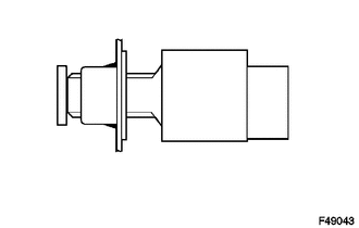
Install the stop light switch assembly to the adjuster until the switch body slightly touches the brake pedal.
- NOTICE:
-
Do not depress the pedal.
b.
0.698,0.125 0.625,0.125
false
0.625,0.125 0.552,0.698
false
1.885,1.25 1.885,1.469
false
0.708,0.063 1.083,0.313
0.375,0.25
10
false
*1
0.5,1.708 0.813,1.99
0.313,0.281
10
false
*a
1.823,1.49 2.115,1.729
0.292,0.24
10
false
*2
| *1 | Shaft |
| *2 | Stop Light Switch |
| *a | 1.5 to 2.5 mm |
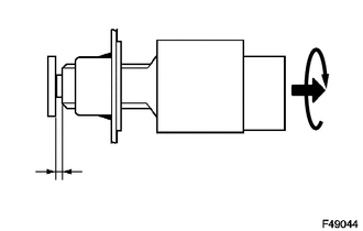
Rotate the stop light switch assembly clockwise so that the clearance is between 1.5 to 2.5 mm (0.0590 to 0.0984 in.) as shown in the illustration.
- Torque:
- 1.5 N*m (15 kgf*cm, 13 in.*lbf)
- NOTICE:
-
Do not depress the pedal.
c.
Check the stop light switch assembly clearance.
- Stop light switch clearance:
1.5 to 2.5 mm (0.059 to 0.098 in.)
d.
Connect the connector to the stop light switch assembly.