RM1840EF
_56
Audio / Visual / Telematics
_009632
NAVIGATION / MULTI INFO DISPLAY
_0052661
NAVIGATION SYSTEM
J
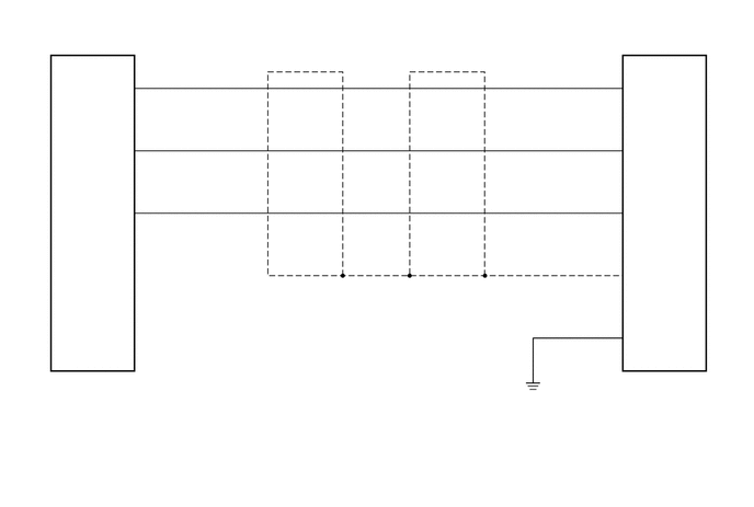
NAVIGATION / MULTI INFO DISPLAY NAVIGATION SYSTEM Microphone Circuit between Microphone and Navigation Receiver Assembly
DESCRIPTION
This circuit sends a microphone signal from the telephone microphone assembly to the navigation receiver assembly.
It also supplies power from the navigation receiver assembly to the telephone microphone assembly.
WIRING DIAGRAM
1.354,1.813 1.531,1.99
0.177,0.177
10
false
2
1.354,1.229 1.531,1.406
0.177,0.177
10
false
3
1.354,0.615 1.531,0.792
0.177,0.177
10
false
4
5.792,3 5.969,3.177
0.177,0.177
10
false
6
0.781,1.927 1.208,2.104
0.427,0.177
10
false
MCO-
0.76,1.354 1.188,1.531
0.427,0.177
10
false
MCO+
0.771,0.76 1.198,0.938
0.427,0.177
10
false
MACC
6.031,3.125 6.458,3.302
0.427,0.177
10
false
SNS2
5.74,2.417 5.917,2.594
0.177,0.177
10
false
18
2.635,2.677 3.24,2.917
0.604,0.24
10
false
Shielded
3.979,2.677 4.583,2.979
0.604,0.302
10
false
Shielded
6.031,2.542 6.458,2.719
0.427,0.177
10
false
SGND
5.74,1.813 5.917,1.99
0.177,0.177
10
false
19
6.031,1.948 6.458,2.125
0.427,0.177
10
false
MIN-
5.792,1.229 5.969,1.406
0.177,0.177
10
false
5
6.031,1.333 6.458,1.51
0.427,0.177
10
false
MIN+
5.792,0.625 5.969,0.802
0.177,0.177
10
false
4
0.302,3.604 0.594,3.76
0.292,0.156
10
false
N2
0.302,3.771 2.375,4.146
2.073,0.375
10
false
Map Light Assembly (Telephone Microphone Assembly)
5.719,3.604 6.292,3.76
0.573,0.156
10
false
G152
6.031,0.729 6.458,0.906
0.427,0.177
10
false
MACC
5.719,3.771 7,4.146
1.281,0.375
10
false
Navigation Receiver Assembly
PROCEDURE
1.CHECK HARNESS AND CONNECTOR (NAVIGATION RECEIVER ASSEMBLY - MAP LIGHT ASSEMBLY)
a.
Disconnect the G152 navigation receiver assembly connector.
b.
Disconnect the N2 map light assembly connector.
c.
Measure the resistance according to the value(s) in the table below.
- Standard Resistance:
Tester Connection Condition Specified Condition G152-4 (MACC) - N2-4 (MACC) Always Below 1 Ω G152-5 (MIN+) - N2-3 (MCO+) Always Below 1 Ω G152-19 (MIN-) - N2-2 (MCO-) Always Below 1 Ω G152-18 (SNS2) - Body ground Always Below 1 Ω G152-4 (MACC) - Body ground Always 10 kΩ or higher G152-5 (MIN+) - Body ground Always 10 kΩ or higher G152-19 (MIN-) - Body ground Always 10 kΩ or higher
- Result:
Proceed to OK NG
OK
2.CHECK NAVIGATION RECEIVER ASSEMBLY
NG
REPAIR OR REPLACE HARNESS OR CONNECTOR
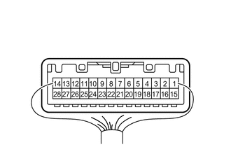
2.CHECK NAVIGATION RECEIVER ASSEMBLY
a.
1.448,0.198 2,0.5
0.552,0.302
2.021,1.344 1.594,0.688
1.594,0.688 1.458,0.688
true
2.219,1.208 2.344,0.552
2.344,0.552 2.448,0.552
true
2.177,1.438 2.365,1.865
2.365,1.865 2.479,1.865
true
0.094,0.073 0.365,0.281
0.271,0.208
10
false
*a
1.135,0.615 1.563,0.771
0.427,0.156
10
false
MIN-
2.5,0.479 2.927,0.635
0.427,0.156
10
false
MACC
1.542,0.26 1.927,0.417
0.385,0.156
10
false
G152
2.542,1.792 2.969,1.948
0.427,0.156
10
false
SGND
| *a | Component without harness connected
(Navigation Receiver Assembly) |
Disconnect the G152 navigation receiver assembly connector.
b.
Measure the resistance according to the value(s) in the table below.
- Standard Resistance:
Tester Connection Condition Specified Condition G152-18 (SGND) - Body ground Always Below 1 Ω G152-19 (MIN-) - Body ground Always Below 1 Ω
c.
Measure the voltage according to the value(s) in the table below.
- Standard Voltage:
Tester Connection Switch Condition Specified Condition G152-4 (MACC) - Body ground Ignition switch ACC 4 to 6 V
- Result:
Proceed to OK NG
OK
PROCEED TO NEXT SUSPECTED AREA SHOWN IN PROBLEM SYMPTOMS TABLE
Click hereAudio / Visual / Telematics>NAVIGATION / MULTI INFO DISPLAY>NAVIGATION SYSTEM>PROBLEM SYMPTOMS TABLE
NG
REPAIR OR REPLACE HARNESS OR CONNECTOR