METER / GAUGE / DISPLAY METER / GAUGE SYSTEM Fuel Receiver Gauge Malfunction
CAUTION / NOTICE / HINT
The fuel sender gauge has a variable resistance mechanism. The resistance decreases when the fuel amount increases, and the resistance increases when the fuel amount decreases. The fuel receiver gauge changes based on the resistance of the fuel sender gauge.
- NOTICE:
-
When the combination meter is removed or replaced, its connector is disconnected or fuel is added, the fuel receiver gauge display will return to normal within a maximum of 16 minutes after the ignition switch is turned to ON or when vehicle speed is input.
WIRING DIAGRAM
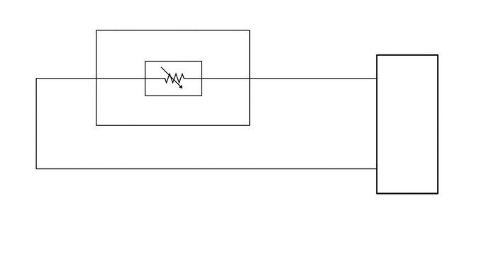
PROCEDURE
Disconnect the G19 combination meter assembly connector.
Disconnect the L4 fuel suction with pump and gauge tube assembly*1, *3 or fuel vent tube sub-assembly*2 connector.
*1: for 2TR-FE, 2TR-FBE
*2: for 1KD-FTV, 2KD-FTV
*3: for 1GR-FE
Measure the resistance according to the value(s) in the table below.
- Standard Resistance:
Tester Connection Condition Specified Condition G19-2 (ES) - L4-3 (FE) Always Below 1 Ω G19-3 (L) - L4-2 (FS) Always Below 1 Ω G19-2 (ES) - G19-3 (L) Always 10 kΩ or higher G19-2 (ES) - Body ground Always 10 kΩ or higher G19-3 (L) - Body ground Always 10 kΩ or higher
- Result:
Proceed to OK NG
OK
NG
Check the engine type.
- Result:
Result Proceed to for 2TR-FBE A except 2TR-FBE B
A
B
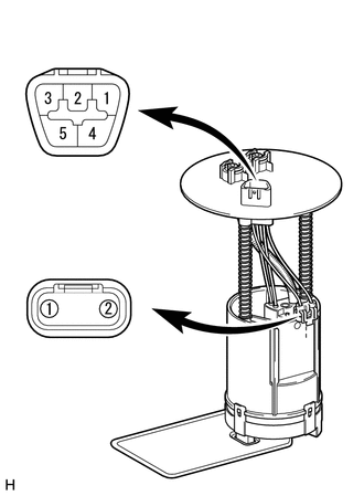
| *a | Upper Side |
| *b | Lower Side
(to Fuel Sender Gauge Assembly) |
| *c | Connector A |
| *d | Connector B |
Remove the fuel vent tube sub-assembly.
Click hereEngine / Hybrid System>2TR-FBE FUEL>FUEL SENDER GAUGE ASSEMBLY(for Fuel Main Tank)>REMOVAL
Measure the resistance according to the value(s) in the table below.
- Standard Resistance:
Tester Connection Condition Specified Condition A-2 - B-1 Always Below 1 Ω A-3 - B-2 Always Below 1 Ω A-2 - A-3 Always 10 kΩ or higher
- Result:
Proceed to OK NG
OK
NG
Click hereEngine / Hybrid System>2TR-FBE FUEL>FUEL SENDER GAUGE ASSEMBLY(for Fuel Main Tank)>REMOVAL
Remove the fuel sender gauge assembly.
Click hereEngine / Hybrid System>2TR-FBE FUEL>FUEL SENDER GAUGE ASSEMBLY(for Fuel Main Tank)>REMOVAL
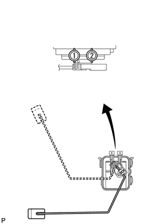
| *a | Front view of wire harness connector
(to Fuel Sender Gauge Assembly) |
| *b | Float Position F (Upper) |
| *c | Float Position E (Lower) |
Measure the resistance according to the value(s) in the table below.
- Standard Resistance:
Tester Connection Condition Specified Condition 1 - 2 Float position F (upper) 13.5 to 16.5 Ω Float position E (lower) 401.8 to 418.2 Ω
- Result:
Proceed to OK NG
OK
NG
Click hereEngine / Hybrid System>2TR-FBE FUEL>FUEL SENDER GAUGE ASSEMBLY(for Fuel Main Tank)>REMOVAL
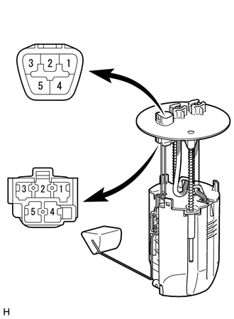
| *a | Upper Side |
| *b | Lower Side
(to Fuel Sender Gauge Assembly) |
| *c | Connector A |
| *d | Connector B |
Remove the fuel suction with pump and gauge tube assembly.
for 1KD-FTV
Click hereEngine / Hybrid System>1KD-FTV FUEL>FUEL SENDER GAUGE ASSEMBLY>REMOVAL
for 2KD-FTV
Click hereEngine / Hybrid System>2KD-FTV FUEL>FUEL SENDER GAUGE ASSEMBLY>REMOVAL
for 1GR-FE
Click hereEngine / Hybrid System>1GR-FE FUEL>FUEL SENDER GAUGE ASSEMBLY>REMOVAL
for 2TR-FE
Click hereEngine / Hybrid System>2TR-FE FUEL>FUEL SENDER GAUGE ASSEMBLY>REMOVAL
Measure the resistance according to the value(s) in the table below.
- Standard Resistance:
Tester Connection Condition Specified Condition A-2 - B-2 Always Below 1 Ω A-3 - B-1 Always Below 1 Ω A-2 - A-3 Always 10 kΩ or higher
- Result:
Result Proceed to OK A NG (for 1KD-FTV) B NG (for 2KD-FTV) C NG (for 1GR-FE) D NG (for 2TR-FE) E
A
B
C
D
E
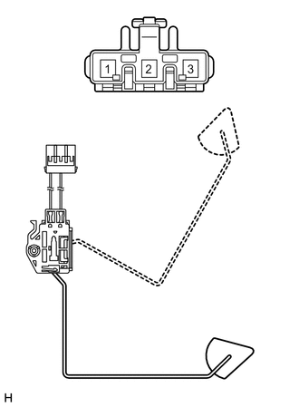
| *a | Front view of wire harness connector
(to Fuel Sender Gauge Assembly) |
| *b | Float Position F (Upper) |
| *c | Float Position E (Lower) |
Remove the fuel sender gauge assembly.
for 1KD-FTV
Click hereEngine / Hybrid System>1KD-FTV FUEL>FUEL SENDER GAUGE ASSEMBLY>REMOVAL
for 2KD-FTV
Click hereEngine / Hybrid System>2KD-FTV FUEL>FUEL SENDER GAUGE ASSEMBLY>REMOVAL
for 1GR-FE
Click hereEngine / Hybrid System>1GR-FE FUEL>FUEL SENDER GAUGE ASSEMBLY>REMOVAL
for 2TR-FE
Click hereEngine / Hybrid System>2TR-FE FUEL>FUEL SENDER GAUGE ASSEMBLY>REMOVAL
Measure the resistance according to the value(s) in the table below.
- Standard Resistance:
Tester Connection Condition Specified Condition 1 - 2 Float position F (upper) 3 to 5 Ω Float position E (lower) 109 to 111 Ω
- Result:
Result Proceed to OK A NG (for 1KD-FTV) B NG (for 2KD-FTV) C NG (for 1GR-FE) D NG (for 2TR-FE) E
A
B
C
D
E