2TR-FBE INTAKE / EXHAUST INTAKE MANIFOLD INSTALLATION
PROCEDURE

 1.INSTALL INTAKE MANIFOLD
Install the purge line hose to the intake manifold.
Install the 2 wire harness clamp brackets to the intake manifold with the 2 bolts.
- Torque:
- 8.0 N*m (82 kgf*cm, 71 in.*lbf)
Apply gasoline to 4 new O-rings. Then install the 4 O-rings to the No. 1 fuel pipe sub-assembly.
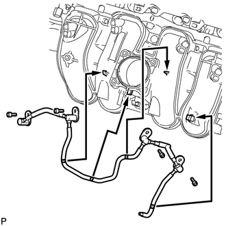
| *1 | Paint Mark (White) |
Set the No. 1 fuel pipe sub-assembly against the 4 protrusions and install it with the 4 bolts.
- Torque:
- 10 N*m (102 kgf*cm, 7 ft.*lbf)
- NOTICE:
- ·
Set the areas of the fuel pipe marked with white paint marks against the protrusions of the intake manifold from the directions indicated by the arrows in the illustration.
·Make sure the fuel pipe does not become deformed when installing it.
Install a new gasket to the intake manifold.
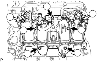

|
Bolt |

|
Nut |
Install the intake manifold with the 5 bolts and 2 nuts, and tighten the bolts and nuts in the sequence shown in the illustration.
- Torque:
- 25 N*m (255 kgf*cm, 18 ft.*lbf)
Connect the No. 3 PCV hose and vacuum hose to the intake manifold.
Attach the No. 2 water by-pass hose.
Attach the No. 1 fuel hose to the intake manifold.
Install the clamp.
Attach the 3 wire harness clamps to the 2 wire harness clamp brackets.
2.INSTALL PURGE VSV
3.INSTALL FRONT UPPER FENDER APRON SEAL
Install the front upper fender apron seal with the 5 clips.
4.INSTALL THROTTLE BODY WITH MOTOR ASSEMBLY
5.INSTALL STARTER ASSEMBLY
6.CONNECT CABLE TO NEGATIVE BATTERY TERMINAL
- NOTICE:
-
When disconnecting the cable, some systems need to be initialized after the cable is reconnected (See page General>INTRODUCTION>REPAIR INSTRUCTION>INITIALIZATION).
7.INSPECT FOR FUEL LEAK (for Fuel Sub Tank)