Home › Steering › STEERING COLUMN › STEERING PAD SWITCH › from 2013.10
RM1840EF _55 Steering _009629 STEERING COLUMN _0052645 STEERING PAD SWITCH G

STEERING COLUMN  STEERING PAD SWITCH  INSPECTION  


PROCEDURE

Hide 1.INSPECT STEERING PAD SWITCH LH (w/o Multi-information Display)

a.

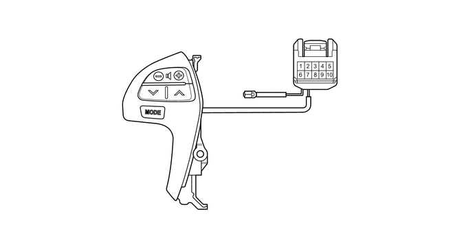
Measure the resistance according to the value(s) in the table below.
C281873
1.677,2.135 2,2.135 2,2.135 2.24,1.75 true 1.563,1.042 1.906,1.042 1.906,1.042 2.177,1.354 true 2.385,1.115 2.229,0.552 2.229,0.552 2.042,0.552 true 2.719,1.083 2.833,0.448 2.833,0.448 3.021,0.448 true 2.823,1.365 3.104,1.031 3.104,1.031 3.313,1.031 true 3.771,1.375 3.875,0.844 3.875,0.844 4.052,0.844 false 5.042,2.135 4.854,2.135 4.854,2.135 4.771,1.167 true 5.25,1.771 5.031,1.771 5.031,1.771 4.885,1.177 true 5.01,1.177 5.156,1.458 5.156,1.458 5.313,1.458 true 4.99,0.958 5.167,0.448 5.167,0.448 5.344,0.448 true 4.542,0.958 4.396,0.438 4.396,0.438 4.219,0.438 true 3.083,0.354 3.396,0.51 0.313,0.156 10 false *1 1.844,0.458 2.156,0.615 0.313,0.156 10 false *2 3.375,0.938 3.688,1.094 0.313,0.156 10 false *3 1.354,0.948 1.667,1.104 0.313,0.156 10 false *4 1.458,2.042 1.771,2.198 0.313,0.156 10 false *5 4.094,0.75 4.406,0.906 0.313,0.156 10 false *6 5.125,2.063 5.583,2.26 0.458,0.198 10 false EAU 5.313,1.677 5.771,1.875 0.458,0.198 10 false AU2 5.375,1.354 5.833,1.552 0.458,0.198 10 false AU1 5.417,0.354 6.031,0.552 0.615,0.198 10 false IL+2 3.979,0.344 4.292,0.542 0.313,0.198 10 false HO
*1 Volume+ Switch *2 Volume- Switch
*3 Seek+ Switch *4 Seek- Switch
*5 MODE Switch *6 Horn Wire


Standard Resistance:
Tester Connection Switch Condition Specified Condition
9 (AU2) - 8 (EAU) No switch pushed 95 to 105 kΩ
9 (AU2) - 8 (EAU) MODE switch pushed Below 2.5 Ω
10 (AU1) - 8 (EAU) No switch pushed 95 to 105 kΩ
10 (AU1) - 8 (EAU) Seek+ switch pushed Below 2.5 Ω
10 (AU1) - 8 (EAU) Seek- switch pushed 312.6 to 345.5 Ω
10 (AU1) - 8 (EAU) Volume+ switch pushed 950 to 1050 Ω
10 (AU1) - 8 (EAU) Volume- switch pushed 2954.5 to 3265.5 Ω
1 (HO) - Horn wire Always Below 2.5 Ω


If the result is not as specified, replace the steering pad switch assembly.


b.

Check the illumination.

i.

Connect the battery positive (+) lead to terminal IL+2 and the negative (-) lead to terminal EAU of the steering pad switch assembly connector.


ii.

Check that the switch illumination comes on.

OK:

Steering pad switch illumination comes on.


If the result is not as specified, replace the steering pad switch assembly.


Hide 2.INSPECT STEERING PAD SWITCH ASSEMBLY (w/ Multi-information Display)

a.

w/o Voice Control Switch:

i.

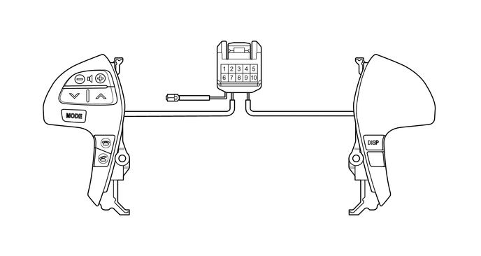
Measure the resistance according to the value(s) in the table below.
C281874
0.625,2.156 0.802,2.156 0.802,2.156 1.021,1.781 true 0.573,1.115 0.75,1.115 0.75,1.115 0.969,1.385 true 1.177,1.146 1.083,0.688 1.083,0.688 0.896,0.688 true 1.49,1.104 1.698,0.49 1.698,0.49 1.896,0.49 true 1.594,1.396 1.865,1.042 1.865,1.042 2,1.042 true 2.563,1.406 2.677,1.021 2.677,1.021 2.823,1.021 false 0.969,2.448 1.156,2.448 1.156,2.448 1.469,2.167 true 0.917,2.823 1.125,2.823 1.125,2.823 1.448,2.438 true 5.656,2.177 5.865,2.531 5.865,2.531 6.156,2.531 true 3,2.021 3.219,2.021 3.219,2.021 3.448,1.188 true 3.875,2.333 3.708,2.333 3.708,2.333 3.563,1.188 true 4.104,1.99 3.906,1.99 3.906,1.99 3.667,1.177 true 3.781,1.188 3.938,1.51 3.938,1.51 4.115,1.51 true 3.781,0.979 4,0.51 4,0.51 4.198,0.51 true 3.333,0.979 3.188,0.51 3.188,0.51 3.021,0.51 true 1.948,0.396 2.26,0.552 0.313,0.156 10 false *1 0.698,0.604 1.01,0.76 0.313,0.156 10 false *2 2.042,0.948 2.354,1.104 0.313,0.156 10 false *3 0.385,1.031 0.698,1.188 0.313,0.156 10 false *4 0.438,2.083 0.75,2.24 0.313,0.156 10 false *5 0.771,2.365 1.083,2.521 0.313,0.156 10 false *6 0.719,2.75 1.031,2.906 0.313,0.156 10 false *7 6.208,2.438 6.521,2.594 0.313,0.156 10 false *8 2.865,0.927 3.177,1.083 0.313,0.156 10 false *9 2.646,1.938 3.26,2.135 0.615,0.198 10 false DISP 3.948,2.25 4.406,2.448 0.458,0.198 10 false EAU 4.167,1.906 4.625,2.104 0.458,0.198 10 false AU2 4.167,1.427 4.625,1.625 0.458,0.198 10 false AU1 4.26,0.427 4.875,0.625 0.615,0.198 10 false IL+2 2.792,0.427 3.104,0.625 0.313,0.198 10 false HO
*1 Volume+ Switch *2 Volume- Switch
*3 Seek+ Switch *4 Seek- Switch
*5 MODE Switch *6 On Hook Switch (w/ hook switch)
*7 Off Hook Switch (w/ hook switch) *8 DISP Switch
*9 Horn Wire - -


Standard Resistance:
Tester Connection Switch Condition Specified Condition
9 (AU2) - 8 (EAU) No switch pushed 95 to 105 kΩ
9 (AU2) - 8 (EAU) MODE switch pushed Below 2.5 Ω
9 (AU2) - 8 (EAU) On hook switch pushed 312.6 to 345.5 Ω
9 (AU2) - 8 (EAU) Off hook switch pushed 950 to 1050 Ω
10 (AU1) - 8 (EAU) No switch pushed 95 to 105 kΩ
10 (AU1) - 8 (EAU) Seek+ switch pushed Below 2.5 Ω
10 (AU1) - 8 (EAU) Seek- switch pushed 312.6 to 345.5 Ω
10 (AU1) - 8 (EAU) Volume+ switch pushed 950 to 1050 Ω
10 (AU1) - 8 (EAU) Volume- switch pushed 2954.5 to 3265.5 Ω
7 (DISP) - 8 (EAU) DISP switch pushed Below 2.5 Ω
1 (HO) - Horn wire Always Below 2.5 Ω


If the result is not as specified, replace the steering pad switch assembly.


ii.

Connect the battery positive (+) lead to terminal IL+2 and the negative (-) lead to terminal EAU of the steering pad switch assembly connector.


iii.

Check that the switch illumination comes on.

OK:

Steering pad switch illumination comes on.


If the result is not as specified, replace the steering pad switch assembly.


b.

w/ Voice Control Switch:

i.

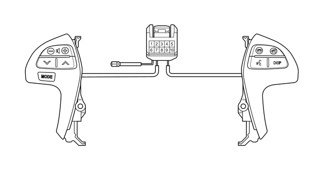
Measure the resistance according to the value(s) in the table below.
C285784
1.521,1.292 1.802,0.927 1.802,0.927 1.958,0.927 true 1.417,1.021 1.563,0.427 1.563,0.427 1.719,0.427 true 1.073,1.042 0.865,0.448 0.865,0.448 0.729,0.448 true 0.844,1.333 0.615,0.781 0.615,0.781 0.479,0.781 true 0.844,1.656 0.5,2.01 0.5,2.01 0.365,2.01 true 2.458,1.313 2.542,0.813 2.542,0.813 2.698,0.813 true 5.396,1.385 5,1.01 5,1.01 4.865,1.01 true 6.083,1.354 6.365,0.99 6.365,0.99 6.521,0.99 true 5.854,1.042 6.135,0.677 6.135,0.677 6.292,0.677 true 5.531,1.01 5.323,0.417 5.323,0.417 5.188,0.417 true 3.698,0.906 3.823,0.427 3.823,0.427 3.979,0.427 true 3.219,0.896 3.125,0.375 3.125,0.375 2.979,0.375 true 3.688,1.104 3.854,1.344 3.854,1.344 4.01,1.344 true 3.573,1.104 3.75,1.802 3.75,1.802 3.906,1.802 true 3.479,1.104 3.542,2.021 3.542,2.021 3.698,2.021 true 3.344,1.104 3.208,1.906 3.208,1.906 3.063,1.906 true 1.76,0.333 2.073,0.49 0.313,0.156 10 false *1 0.563,0.333 0.875,0.49 0.313,0.156 10 false *2 2.021,0.823 2.333,0.979 0.313,0.156 10 false *3 0.313,0.698 0.625,0.854 0.313,0.156 10 false *4 0.188,1.927 0.5,2.083 0.313,0.156 10 false *5 5.031,0.323 5.344,0.479 0.313,0.156 10 false *6 6.313,0.583 6.625,0.74 0.313,0.156 10 false *7 4.719,0.927 5.031,1.083 0.313,0.156 10 false *8 6.531,0.906 6.844,1.063 0.313,0.156 10 false *9 2.74,0.729 3.208,0.885 0.469,0.156 10 false *10 2.74,0.281 3.052,0.479 0.313,0.198 10 false HO 4.042,0.344 4.469,0.552 0.427,0.208 10 false IL+2 4.052,1.26 4.406,1.458 0.354,0.198 10 false AU1 3.958,1.708 4.313,1.906 0.354,0.198 10 false AU2 3.74,1.948 4.156,2.146 0.417,0.198 10 false EAU 2.729,1.813 3.198,2.021 0.469,0.208 10 false DISP
*1 Volume+ Switch *2 Volume- Switch
*3 Seek+ Switch *4 Seek- Switch
*5 MODE Switch *6 On Hook Switch
*7 Off Hook Switch *8 Voice Switch
*9 DISP Switch *10 Horn Wire


Standard Resistance:
Tester Connection Switch Condition Specified Condition
9 (AU2) - 8 (EAU) No switch pushed 95 to 105 kΩ
9 (AU2) - 8 (EAU) MODE switch pushed Below 2.5 Ω
9 (AU2) - 8 (EAU) On hook switch pushed 312.6 to 345.5 Ω
9 (AU2) - 8 (EAU) Off hook switch pushed 950 to 1050 Ω
9 (AU2) - 8 (EAU) Voice switch pushed 2954.5 to 3265.5 Ω
10 (AU1) - 8 (EAU) No switch pushed 95 to 105 kΩ
10 (AU1) - 8 (EAU) Seek+ switch pushed Below 2.5 Ω
10 (AU1) - 8 (EAU) Seek- switch pushed 312.6 to 345.5 Ω
10 (AU1) - 8 (EAU) Volume+ switch pushed 950 to 1050 Ω
10 (AU1) - 8 (EAU) Volume- switch pushed 2954.5 to 3265.5 Ω
7 (DISP) - 8 (EAU) DISP switch pushed Below 2.5 Ω
1 (HO) - Horn wire Always Below 2.5 Ω


If the result is not as specified, replace the steering pad switch assembly.


ii.

Connect the battery positive (+) lead to terminal IL+2 and the negative (-) lead to terminal EAU of the steering pad switch assembly connector.


iii.

Check that the switch illumination comes on.

OK:

Steering pad switch illumination comes on.


If the result is not as specified, replace the steering pad switch assembly.