RM1840EF
_59
Vehicle Exterior
_009653
MIRROR (EXT)
_0052807
OUTER MIRROR SWITCH
A
MIRROR (EXT) OUTER MIRROR SWITCH REMOVAL
PROCEDURE

 1.REMOVE NO. 1 SWITCH HOLE BASE
2,1.219 2.656,1.219
false
2.74,1.177 3.052,1.375
0.313,0.198
10
false
*1
| *1 | Protective Tape |
a.
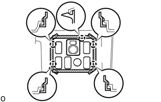
Place protective tape as shown in the illustration.
b.
Using moulding remover D, detach the 5 claws.
c.
Remove the No. 1 switch hole base and disconnect the connectors.
2.REMOVE OUTER MIRROR SWITCH ASSEMBLY
a.
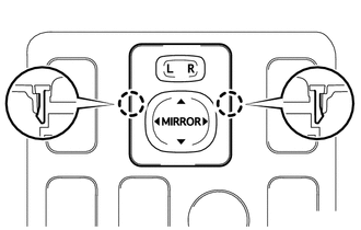
Detach the 2 claws and remove the outer mirror switch assembly from the No. 1 switch hole base.
3.REMOVE NO. 2 OUTER MIRROR SWITCH ASSEMBLY
a.
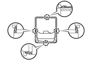
Using a screw driver, Detach the 4 claws and remove the bezel from the No. 2 outer mirror switch assembly.