Fuel Injector Assembly
The fuel injector assembly is shaped to form a long nozzle. This shortens the distance from the fuel injector assembly to the intake valve, which prevents the fuel from adhering to the intake port walls and reduces HC exhaust emissions. Depending on the type of fuel that is used, a 12-hole type fuel injector assembly is provided.
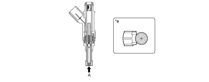
Text in Illustration *a View from A - -
Fuel Delivery Pipe Sub-assembly
The fuel delivery pipe sub-assembly is made of aluminum die-cast to reduce weight.
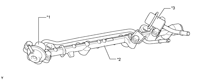
Text in Illustration *1 Fuel Pressure Regulator *2 Fuel Delivery Pipe Sub-assembly *3 Fuel Pulsation Damper - -
Main Tank Fuel Pump Assembly
A compact, alcohol-resistant main tank fuel pump assembly integrating a fuel sender gauge and a main tank fuel pump is used.
A sealed type fuel sender gauge is used to protect metal surfaces from being corroded by alcohol fuel.
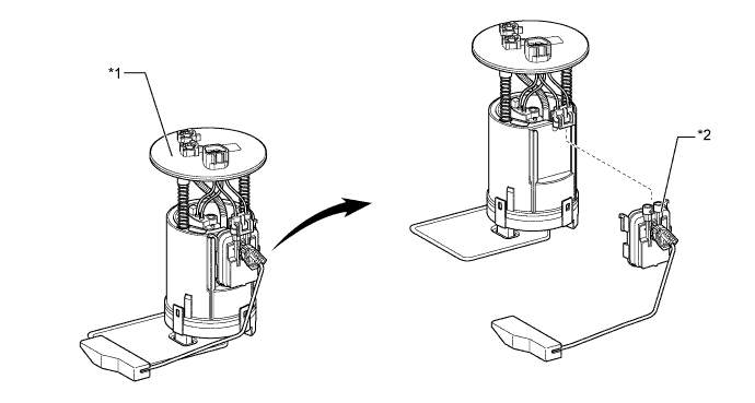
Text in Illustration *1 Main Tank Fuel Pump Assembly *2 Fuel Sender Gauge Assembly
Fuel Sub-tank, Sub-tank Fuel Pump and Solenoid Valves
A fuel sub-tank with a sub-tank fuel pump is used.
The capacity of the fuel sub-tank is 0.6 liters (0.63 US qts, 0.53 Imp. qts).
The fuel sub-tank is provided with an EVAP port.
Solenoid valves which control fuel flow are used.
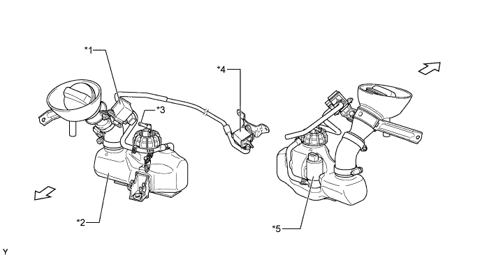
Text in Illustration *1 No. 1 Solenoid Valve *2 Fuel Sub-tank *3 EVAP Port *4 No. 2 Solenoid Valve *5 Sub-tank Fuel Pump - - 
Front - - - HINT:
- The fuel sub-tank is supplied with fuel of E22 (22% ethanol.)
Fuel Jet
A fuel jet is installed on the intake manifold.
When the sub-tank system is operating, the fuel jet injects the fuel which is in the fuel sub-tank into the intake port.
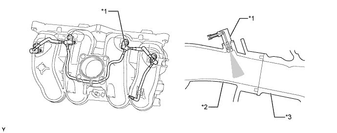
Text in Illustration *1 Fuel Jet *2 Intake Manifold *3 Cylinder Head - -