FUEL SYSTEM > DETAILS |
| SYSTEM CONTROL |
Common-rail System
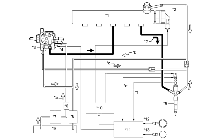
In this system, the highly pressurized fuel supplied by the supply pump is stored in the common-rail, and the ECM sends signals to the injectors via the injector driver in order to control the injection timing and injection volume.
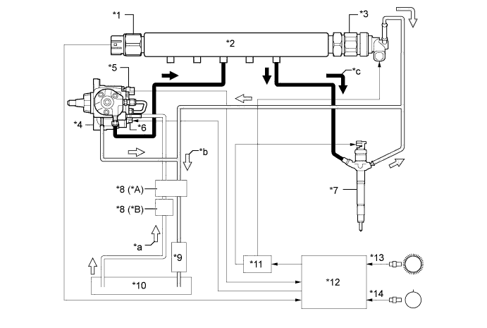
| *A | Models Compliant with EURO 4 Emission Regulations | *B | Except Models Compliant with EURO 4 Emission Regulations |
| *1 | Fuel Pressure Sensor | *2 | Common-rail Assembly |
| *3 | Pressure Discharge Valve | *4 | Supply Pump Assembly |
| *5 | Fuel Temperature Sensor | *6 | Suction Control Valve (SCV) |
| *7 | Injector Assembly | *8 | Fuel Filter Assembly |
| *9 | Fuel Cooler | *10 | Fuel Tank |
| *11 | Injector Driver | *12 | ECM |
| *13 | Crank Position Sensor (NE Signal) | *14 | Camshaft Position Sensor (G Signal) |
| *a | Fuel (Suction) | *b | Fuel (Return) |
| *c | Fuel (High Pressure) | - | - |

| *1 | Common-rail Assembly | *2 | Pressure Discharge Valve |
| *3 | Supply Pump Assembly | *4 | Suction Control Valve (SCV) |
| *5 | Injector Assembly | *6 | 2nd Fuel Filter |
| *7 | Fuel Filter Assembly | *8 | Fuel Cooler |
| *9 | Fuel Tank | *10 | Injector Driver |
| *11 | ECM | *12 | Crank Position Sensor (NE Signal) |
| *13 | Camshaft Position Sensor (G Signal) | - | - |
| *a | Fuel (Suction) | *b | Fuel (Return) |
| *c | Fuel (High Pressure) | *d | Fuel (Back Pressure) |
| *e | INJ Communication (Fuel Temperature Signal and Memory IC Communication) | *f | Fuel Pressure Signal |
| CONSTRUCTION |
Supply Pump Assembly
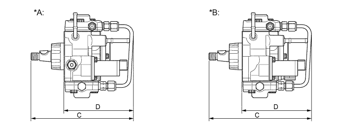
An HP3 type supply pump is used.

| *A | Model Compliant with Tier 1.5 Emission Regulations | *B | Except Model Compliant with Tier 1.5 Emission Regulations |
| Type | HP3 | |
| Length | C | 190.2 mm (7.49 in.) |
| D | 129.0 mm (5.08 in.) | |
| SCV | 1 | |
| Plunger | φ 8.5 mm x 2 | |
| Weight | 3800 g (8.38 lb) | |
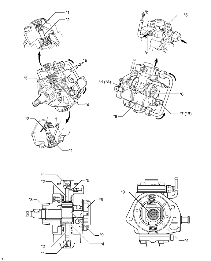
The supply pump consists of an eccentric camshaft, a ring cam, 2 plungers, 4 check valves, a Suction Control Valve (SCV), a fuel temperature sensor*, and a feed pump.
The 2 plungers are placed opposite each other outside of the ring cam.

| *A | Models Compliant with Tier 1.5 Emission Regulations | *B | Except Models Compliant with Tier 1.5 Emission Regulations |
| *1 | Check Valve (for Suction) | *2 | Plunger |
| *3 | Eccentric Camshaft | *4 | Ring Cam |
| *5 | Check Valve (for Discharge) | *6 | Feed Pump |
| *7 | Fuel Temperature Sensor | *8 | SCV |
| *9 | Eccentric Cam Portion | - | - |
| *a | From Fuel Tank (for Suction) | *b | To Fuel Tank (for Return) |
| *c | To Common-rail | *d | To Injector Assembly (for Back Pressure) |
Common-rail Assembly
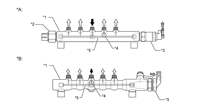
The function of the common-rail is to store the fuel that has been pressurized by the supply pump.
Except on the models compliant with Tier 1.5 emission regulations, the common-rail is provided with a fuel pressure sensor and pressure discharge valve.
On the models compliant with Tier 1.5 emission regulations, the common-rail is provided with a pressure discharge valve.
The fuel pressure sensor detects the fuel pressure in the common-rail.
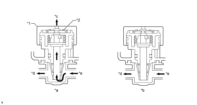
The pressure discharge valve regulates the fuel pressure. In the pressure discharge valve, the plunger opens and closes in accordance with the actuation signals from the injector driver. Thus, it regulates pressure by releasing excess pressure from the common-rail. In addition, it has a pressure reduction function in case of emergency.
Internally, the common-rail contains a main hole and 5 branch holes that intersect the main hole. Each branch hole functions as an orifice that dampens the fluctuation of the fuel pressure.

| *A | Except Models Compliant with Tier 1.5 Emission Regulations | *B | Models Compliant with Tier 1.5 Emission Regulations |
| *1 | Common-rail Assembly | *2 | Fuel Pressure Sensor |
| *3 | Pressure Discharge Valve | *4 | Branch Hole |
| *5 | Main Hole | - | - |
![]() | From Supply Pump | ![]() | To Injector Assembly |
![]() | To Fuel Tank (Excess Pressure) | - | - |
Injector Assembly
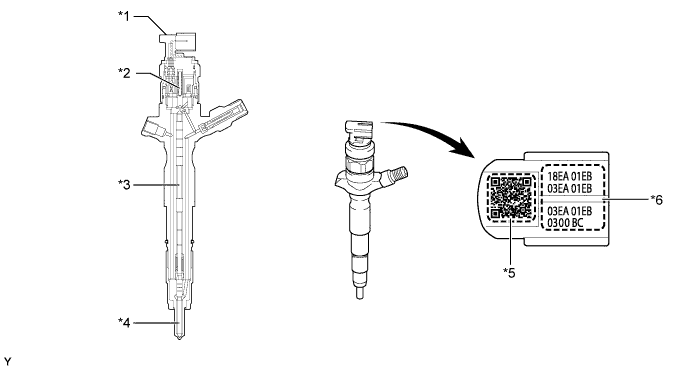
Except on the models compliant with Tier 1.5 emission regulations, each injector assembly consists of a nozzle needle, a piston, and a solenoid valve.
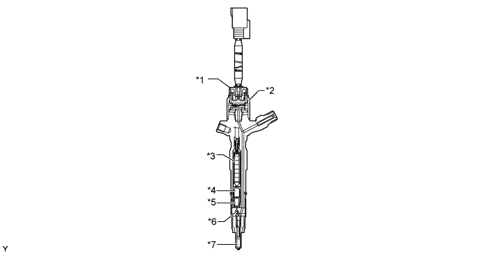
On the models compliant with Tier 1.5 emission regulations, each injector assembly consists of a nozzle needle, 2 pistons, a three-way valve, a piezo actuator, a fuel pressure sensor, a fuel temperature sensor and memory IC. The fuel temperature sensor and memory IC communicate with the ECM.
Except on the models compliant with Tier 1.5 emission regulations, An injector compensation value and a Quick Response (QR) code containing encoded characteristics of the injector are printed on each injector.
On models compliant with Tier 1.5 emission regulations, an injector compensation value and a QR code are not printed on the injector assembly because injection volume is automatically corrected.
On the models compliant with Tier 1.5 emission regulations, the injector assembly is provided with an auto-learning function. Learned values are stored by the injector assembly in its own built-in memory IC.

| *1 | Injector Assembly | *2 | Fuel Temperature Sensor, Fuel Pressure Sensor and Memory IC Portion |
| *3 | Piezo Actuator | *4 | No. 1 Piston |
| *5 | No. 2 Piston | *6 | Three-way Valve |
| *7 | Nozzle Needle | - | - |

| *1 | Injector Assembly | *2 | Solenoid Valve |
| *3 | Piston | *4 | Nozzle Needle |
| *5 | QR Code | *6 | Injector Compensation Value |
Fuel Filter Assembly
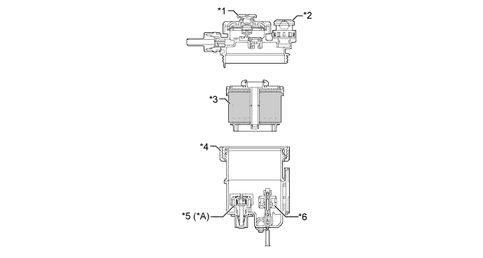
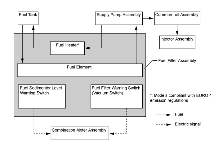
A fuel filter assembly consists of a separate filter element and a filter housing.
A paper filter element that offers high filtering efficiency and captures the minutest particles is used.
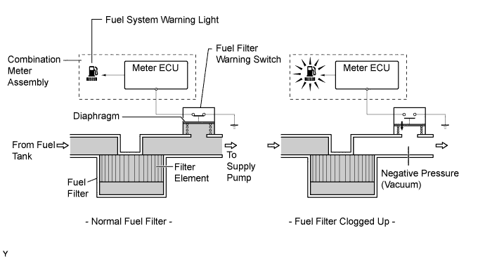
A fuel filter warning switch is provided in the fuel filter assembly.
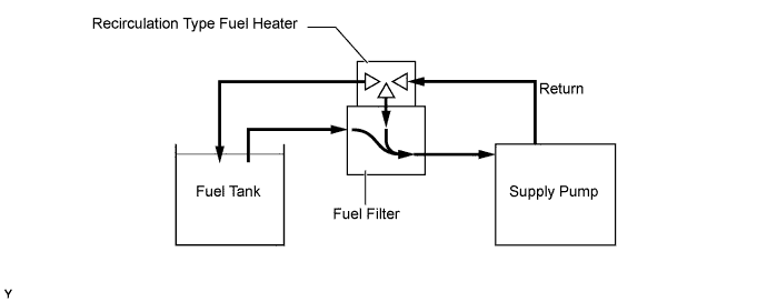
On the models compliant with EURO 4 emission regulations, in order to improve the fuel heating performance, a recirculation type fuel heater is used.

| *A | Models Compliant with EURO 4 Emission Regulations | - | - |
| *1 | Priming Pump | *2 | Fuel Filter Warning Switch (Vacuum Switch) |
| *3 | Filter Element | *4 | Filter Housing |
| *5 | Fuel Heater | *6 | Fuel Sedimenter Level Warning Switch |
Fuel Cooler
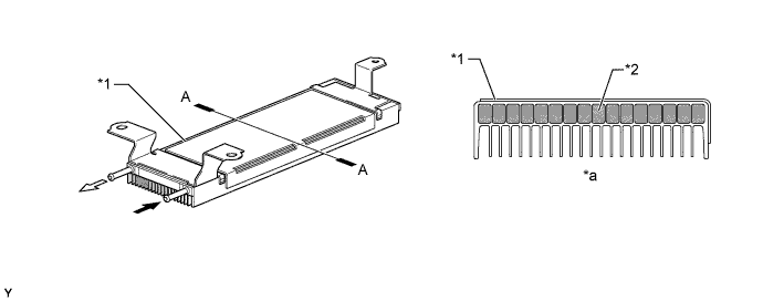
An air-cooled fuel cooler is used.
The fuel cooler, which is provided in the fuel return path, cools the return fuel that has reached a high temperature as a result of the pumping of the supply pump. This prevents the reduction in fuel viscosity that is caused by the rise in fuel temperature, and improves the reliability of the fuel system.

| *1 | Fuel Cooler | *2 | Fuel |
| *a | A - A Cross Section | - | - |
![]() | To Fuel Tank | ![]() | From Engine |
| OPERATION |
Supply Pump Assembly
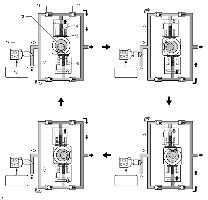
Due to the rotation of the eccentric cam, the ring cam pushes plunger "A" upward as illustrated below. The force of the spring pulls plunger "B" (which is located opposite plunger "A") upward. As a result, plunger "B" draws fuel in, and plunger "A" pumps fuel at the same time.

| *1 | Check Valve (for Suction) | *2 | Check Valve (for Discharge) |
| *3 | Eccentric Cam | *4 | Plunger "A" |
| *5 | Ring Cam | *6 | Plunger "B" |
| *7 | Suction Control Valve (SCV) | *8 | ECM |
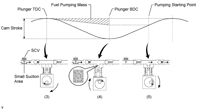
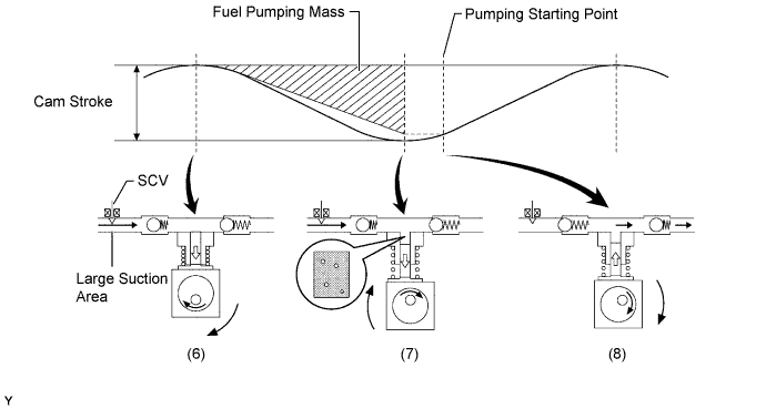
The ECM controls the opening of the SCV in order to regulate the volume of fuel that is pumped by the supply pump to the common-rail. Consequently, the fuel pressure in the common-rail is controlled to the target injection pressure.
When the opening of the SCV is small, the fuel suction area is kept small, which decreases the transferable fuel quantity.
When the plunger strokes fully, however, the suction volume becomes small due to the small suction area.
Pumping will start when the fuel pressure has become higher than the common-rail pressure.

When the opening of the SCV is large, the fuel suction area is kept large, which increases the transferable fuel quantity.
If the plunger strokes fully, the suction volume will increase because the suction area is large.
Pumping will start at the time when the fuel pressure has become higher than the common-rail pressure.

Injector Assembly (Models Compliant with Tier 1.5 Emission Regulations)
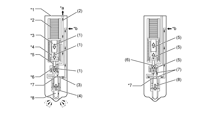
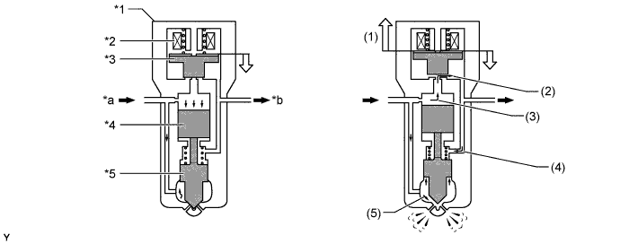
When current is applied to the piezo actuator, the No. 1 piston, No. 2 piston and three-way valve are pushed down.
The orifice on the upper part of the three-way valve opens and the fuel in the control chamber flows out.
The fuel pressure in the control chamber drops.
As a result, the nozzle needle is pushed up due to fuel pressure, causing fuel injection.
Current to the piezo actuator is shut off and the No. 1 and No. 2 pistons and the three-way valve are pushed up due to spring tension.
The orifice on the upper part of the three-way valve closes to stop fuel flow.
The fuel pressure in the control chamber rises.
As a result, the nozzle needle goes down to stop fuel injection.

| *1 | Injector Assembly | *2 | Piezo Actuator |
| *3 | No. 1 Piston | *4 | No. 2 Piston |
| *5 | Orifice | *6 | Three-way Valve |
| *7 | Control Chamber | *8 | Nozzle Needle |
| *a | Return Fuel | *b | Fuel from Common-rail |
Injector Assembly (Except Models Compliant with Tier 1.5 Emission Regulations)
When electrical current is applied to the solenoid coil, it pulls the solenoid valve up.
The orifice of the control chamber opens, allowing the fuel to flow out.
The fuel pressure in the control chamber drops.
Simultaneously, fuel flows from the orifice to the bottom of the piston and raises the piston up (to enhance response).
As a result, the piston raises the nozzle needle to inject fuel.

| *1 | Injector Assembly | *2 | Solenoid Coil |
| *3 | Solenoid Valve | *4 | Piston |
| *5 | Nozzle Needle | - | - |
| *a | Fuel from Common-rail | *b | Return Fuel |
Fuel Filter Assembly
Fuel Filter Warning Switch


Fuel Heater (Models Compliant with EURO 4 Emission Regulations)


| *1 | Fuel Heater | - | - |
| *a | Cold Engine (Recirculation Valve: Open) | *b | Warm Engine (Recirculation Valve: Closed) |
| *c | To Fuel Filter | *d | To Fuel Tank |
| *e | From Supply Pump Assembly | - | - |