Buzzer Function
The table below shows the warning and reminder functions of the buzzer in the combination meter assembly:
Item - Key Reminder
- Light Reminder
- Fuel Sedimenter Warning*
- *: Models with diesel engine
- Key Reminder
Front Seat Belt Warning System
When the ignition switch is ON, this system detects the condition of the seat belts based on the signals from the driver and front passenger seat belt buckle switches and the occupant detection sensor.
If the driver and front passenger seat belt buckle switches are off at this time, the front seat belt warning light will blink.
Occupant Detection Sensor
- The occupant detection sensor, which is enclosed in the seat cushion of the front passenger seat, is used to detect whether or not the front passenger seat is occupied.
- This sensor consists of a construction in which 2 electrode sheets sandwich a spacer. When the occupant is seated, the electrode sheets come in contact with each other through the hole provided in the spacer portion, thus enabling the current to flow.
- The sensor detects whether or not an occupant is seated in the front passenger seat.
- The occupant detection sensor, which is enclosed in the seat cushion of the front passenger seat, is used to detect whether or not the front passenger seat is occupied.
Sub-tank Warning Function
When the meter ECU judges via the fuel sender gauge signal in the sub-tank that the remaining amount of gasoline in the sub-tank is below a certain level, the sub-tank warning light blinks to warn the driver that the amount of gasoline in the sub-tank has decreased.
For drivers who do not use the sub-tank, the sub-tank warning light function can be turned off by the following procedure:
- Turn the ignition switch off when TRIP B is shown.
- Turn the ignition switch ON with the ODO/TRIP switch pressed.
- Hold the ODO/TRIP switch for 10 seconds or more. During this, the sub-tank warning light will blink.
- After 10 seconds, the sub-tank warning light function conditions are displayed as follows:
Sub-tank Warning Light Function On (Default) Off ODO/TRIP Meter 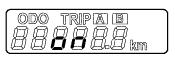
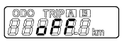
Sub-tank Warning Light Illuminates Off - Pressing the ODO/TRIP switch switches between on and off.
- After off has been displayed, the function can be set to off by leaving the ODO/TRIP switch for approximately 5 seconds.
- When changing the setting to on, conduct the above procedure to set the sub-tank warning light function to on.
- Turn the ignition switch off when TRIP B is shown.