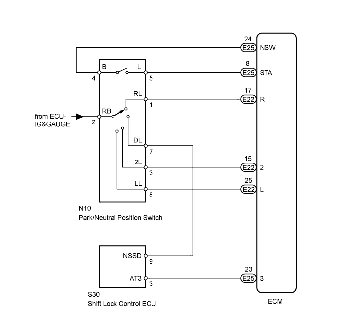
DTC P0705 Transmission Range Sensor Circuit Malfunction (PRNDL Input) |
| DTC No. | DTC Detection Conditions | Trouble Areas |
| P0705 | 2 or more switches are ON simultaneously for P (NSW), R, N (NSW), D, 2 or L positions (2 trip detection logic) |
|
| Tester Display | Measurement Item/Range | Normal Condition | Diagnostic Note |
| Neutral Position SW Signal | Park/neutral position switch status/ ON or OFF | Shift lever is:
| When the shift lever position displayed on the intelligent tester differs from the actual position, the adjustment of the PNP switch or shift cable may be incorrect. |
| Shift SW Status (R Range) | Park/neutral position switch status/ ON or OFF | Shift lever is:
| When the shift lever position displayed on the intelligent tester differs from the actual position, the adjustment of the PNP switch or shift cable may be incorrect. |
| Shift SW Status (2 Range) | Park/neutral position switch status/ ON or OFF | Shift lever is:
| When the shift lever position displayed on the intelligent tester differs from the actual position, the adjustment of the PNP switch or shift cable may be incorrect. |
| Shift SW Status (L Range) | Park/neutral position switch status/ ON or OFF | Shift lever is:
| When the shift lever position displayed on the intelligent tester differs from the actual position, the adjustment of the PNP switch or shift cable may be incorrect. |
| Shift SW Status (3 Range) | Park/neutral position switch status/ ON or OFF | Shift lever is:
| When the shift lever position displayed on the intelligent tester differs from the actual position, the adjustment of the PNP switch or shift cable may be incorrect. |
| 1.INSPECT PARK/NEUTRAL POSITION SWITCH |
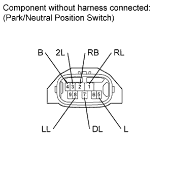 |
Disconnect the N10 park/neutral position switch connector.
Measure the resistance according to the value(s) in the table below.
| Tester Connection | Shift Lever Position | Specified Condition |
| 4 (B) - 5 (L) | P or N | Below 1 Ω |
| 4 (B) - 5 (L) | Not in P or N | 10 kΩ or higher |
| 1 (RL) - 2 (RB) | R | Below 1 Ω |
| 1 (RL) - 2 (RB) | Not in R | 10 kΩ or higher |
| 2 (RB) - 7 (DL) | D | Below 1 Ω |
| 2 (RB) - 7 (DL) | Not in D | 10 kΩ or higher |
| 2 (RB) - 3 (2L) | 2 | Below 1 Ω |
| 2 (RB) - 3 (2L) | Not in 2 | 10 kΩ or higher |
| 2 (RB) - 8 (LL) | L | Below 1 Ω |
| 2 (RB) - 8 (LL) | Not in L | 10 kΩ or higher |
|
| ||||
| OK | |
 |
| 2.INSPECT SHIFT LOCK CONTROL ECU |
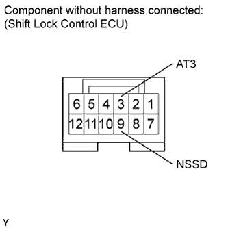 |
Disconnect the S30 ECU connector.
Measure the resistance according to the value(s) in the table below.
| Tester Connection | Shift Lever Position | Specified Condition |
| 9 (NSSD) - 3 (AT3) | D | 10 kΩ or higher |
| 9 (NSSD) - 3 (AT3) | 3 | Below 1 Ω |
|
| ||||
| OK | |
|
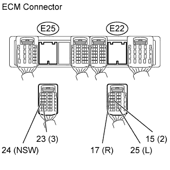
| 3.CHECK WIRE HARNESS (ECM - BATTERY) |
Disconnect the E22 and E25 ECM connectors.
 |
Turn the ignition switch to ON.
Measure the voltage according to the value(s) in the table below
| Tester Connection | Shift Lever Position | Specified Condition |
| E25-24 (NSW) - Body ground | P or N | Below 1 V |
| E25-24 (NSW) - Body ground | Not in P or N | 11 to 14 V |
| E22-17 (R) - Body ground | R | 11 to 14 V* |
| E22-17 (R) - Body ground | Not in R | Below 1 V |
| E25-23 (3) - Body ground | D | 11 to 14 V |
| E25-23 (3) - Body ground | Not in D | Below 1 V |
| E22-15 (2) - Body ground | 2 | 11 to 14 V |
| E22-15 (2) - Body ground | Not in 2 | Below 1 V |
| E22-25 (L) - Body ground | L | 11 to 14 V |
| E22-25 (L) - Body ground | Not in L | Below 1 V |
|
| ||||
| OK | ||
 | ||
| ||
