 |
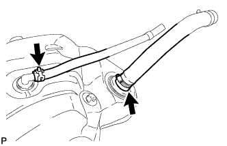
Install the fuel tank to filler pipe hose to the fuel tank.
FUEL TANK > INSTALLATION |
| 1. INSTALL FUEL TANK TO FILLER PIPE HOSE |
|
Install the fuel tank to filler pipe hose to the fuel tank.
| 2. INSTALL FUEL TANK BREATHER HOSE |
Install the fuel tank breather hose to the fuel tank.
| 3. INSTALL FUEL SUCTION WITH PUMP AND GAUGE TUBE ASSEMBLY |
Apply a light coat of gasoline or grease to a new gasket, and install it to the fuel tank.
Install the fuel suction with pump and gauge tube to the fuel tank.
Set the fuel pump gauge retainer on the fuel tank. While holding the fuel suction with pump and gauge tube, tighten the retainer one complete turn by hand.
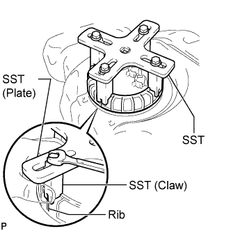 |
Temporarily install SST (plate and 4 claws) to the fuel pump gauge retainer.
While pressing SST (claws) against the fuel pump gauge retainer ribs securely, install the 4 bolts.
Install SST (handle).
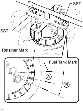 |
Using SST, tighten the retainer until the mark on the retainer aligns with mark A on the fuel tank as shown in the illustration.
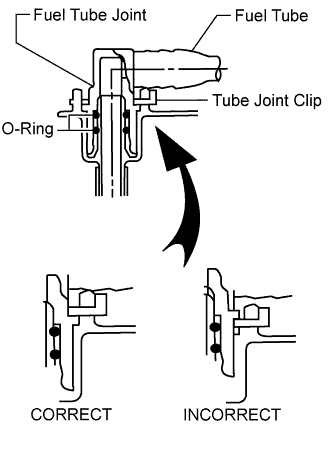
Install the fuel tank return tube and fuel tank main tube to the fuel tank.
Install the 2 fuel tank tubes with the 2 tube joint clips.
| 4. INSTALL NO. 1 FUEL EVAPORATION TUBE SUB-ASSEMBLY |
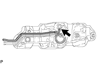 |
Install the No. 1 fuel evaporation tube.
| 5. INSTALL FUEL TANK CUSHION |
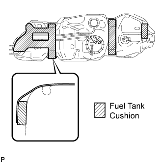 |
Install 4 new fuel tank cushions.
| 6. INSTALL NO. 1 FUEL TANK PROTECTOR SUB-ASSEMBLY |
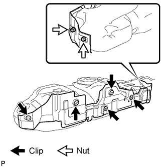 |
Install the No. 1 fuel tank protector with the 5 clips and 2 nuts.
| 7. INSTALL FUEL TANK ASSEMBLY |
Set the fuel tank on a transmission jack and raise the fuel tank.
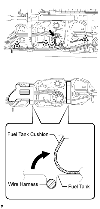 |
Fold back the 2 cushions.
Attach the wire harness to the 4 clamps and connect the fuel pump and sender gauge connector.
Install the 3 fuel tank bands with the 3 pins and 3 clips.
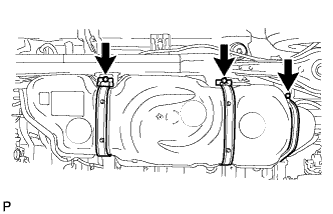 |
Connect the 3 fuel tank bands with the 3 bolts.
| 8. INSTALL FUEL TANK FILLER PIPE |
Install the filler pipe with the bolt and nut.
| 9. CONNECT FUEL TANK TO FILLER PIPE HOSE |
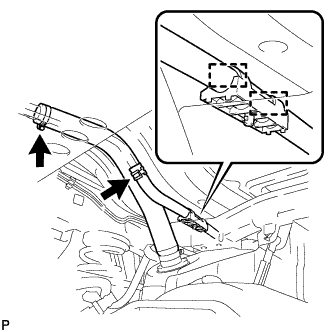 |
Connect the fuel tank to filler pipe hose to the fuel tank filler pipe.
| 10. CONNECT FUEL TANK BREATHER HOSE |
Attach the breather hose to the 2 clamps.
Connect the fuel tank breather hose to the fuel tank filler pipe.
| 11. CONNECT FUEL TANK MAIN TUBE SUB-ASSEMBLY AND FUEL TANK RETURN TUBE |
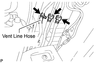 |
Connect the fuel tank return tube connector to the pipe. Then connect the fuel tank main tube connector to the pipe. Push the 2 tube connectors into the pipe until the tube connector makes a "click" sound.
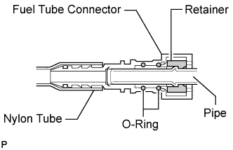
Connect the vent line hose to the fuel pipe.
| 12. INSTALL NO. 3 FUEL TUBE CLAMP |
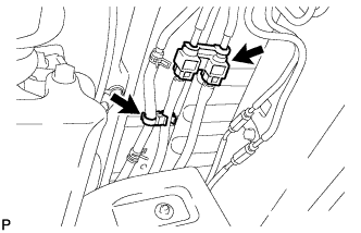 |
Install the 2 tube clamps to the fuel tube.
| 13. INSTALL FUEL TANK PROTECTOR |
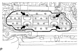 |
Install the fuel tank protector with the 4 nuts.
| 14. INSTALL FUEL TANK CAP ASSEMBLY |
| 15. CONNECT CABLE TO NEGATIVE BATTERY TERMINAL |
| 16. CHECK FOR FUEL LEAKS |
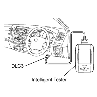 |
Connect the intelligent tester to the DLC3.
Turn the ignition switch ON.
Push the intelligent tester main switch ON.
To perform the Active Test, enter the following menus: Powertrain / Engine and ECT / Active Test / Control the Fuel Pump / Speed.
Check the fuel pump operation.
Check for pressure in the fuel inlet tube from the fuel line. Check that the sound of fuel flowing in the fuel tank can be heard.
If there is no sound, check the integration relay, fuel pump, ECM and wiring connector.
Check for fuel leaks.
Check that there are no fuel leaks after performing maintenance anywhere on the system.
If there are fuel leaks, repair or replace the leaking parts.