 |
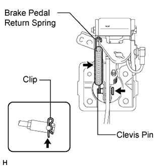
Install the clevis pin and a new clip.
- NOTICE:
- The clip must be installed as shown in the illustration.
BRAKE BOOSTER (w/ VSC) > INSTALLATION |
| 1. INSTALL BRAKE BOOSTER ASSEMBLY |
Install a new gasket to the brake booster.
Install the booster with the 4 nuts.
Install the push rod clevis.
Apply a light coat of lithium soap base glycol grease to the clevis pin.
|
Install the clevis pin and a new clip.
Install the return spring.
Install the vacuum check valve grommet and vacuum check valve to the brake booster.
Connect the vacuum hose.
Install the vacuum warning switch grommet to the brake booster.
Install the vacuum warning switch to the brake booster and connect the vacuum warning switch connector.
| 2. INSPECT AND ADJUST BRAKE BOOSTER PUSH ROD |
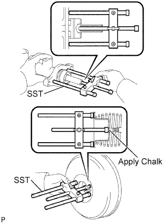 |
Set SST on the master cylinder and lower the rod of SST until it just touches the piston.
Apply chalk to the flat tip of the rod of SST. Turn SST upside down and measure the clearance between the brake booster push rod and SST.
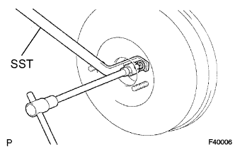 |
If the clearance is not as specified, adjust the length by holding the rod using SST and turning the tip of the rod using a 7 mm socket driver.
| 3. INSTALL BRAKE MASTER CYLINDER SUB-ASSEMBLY |
| 4. FILL RESERVOIR WITH BRAKE FLUID |
| 5. BLEED AIR FROM BRAKE MASTER CYLINDER |
Using a union nut wrench, disconnect the 2 brake lines from the master cylinder.
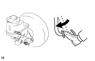 |
Slowly depress and hold the brake pedal.
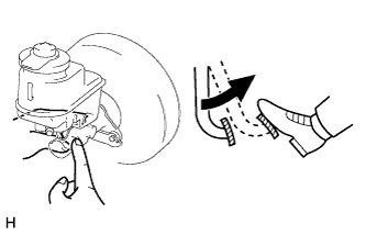 |
Cover the outer holes with your fingers, and release the pedal.
Repeat the 2 previous steps 3 or 4 times.
Using a union nut wrench, connect the 2 brake lines to the master cylinder.
| 6. BLEED AIR FROM BRAKE LINE |
Remove the bleeder plug cap.
Connect a vinyl tube to the bleeder plugs.
Depress the brake pedal several times, and then loosen the bleeder plug with the pedal depressed.
When fluid stops coming out, immediately tighten the bleeder plug. Then release the pedal.
Repeat the 2 previous steps until all the air in the brake fluid is gone.
Tighten the bleeder plug.
Install the cap.
Bleed air from the brake line for each wheel by repeating the above procedures.
| 7. BLEED AIR FROM CLUTCH LINE (for Manual Transmission) |
Remove the brake master cylinder reservoir filler cap assembly.
Add brake fluid to keep the level between the MIN and MAX lines of the reservoir while bleeding the clutch line.
Remove the bleeder plug cap.
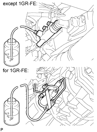 |
Connect a vinyl tube to the bleeder plug.
Depress the clutch pedal several times, and then loosen the bleeder plug with the pedal depressed.
At the point when fluid stops coming out, tighten the bleeder plug, and then release the clutch pedal.
Repeat the previous 2 steps until all the air in the fluid is completely bled out.
Tighten the bleeder plug.
Install the bleeder plug cap.
Check that all the air has been bled out of the clutch line.
Check for brake fluid leaks.
Check the brake fluid level in the reservoir.
w/o VSC:
w/ VSC:
Install the brake master cylinder reservoir filler cap assembly.
| 8. CHECK AND ADJUST BRAKE PEDAL HEIGHT |