 |
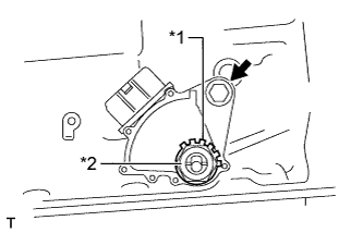
Install the park/neutral position switch to the manual valve shaft.
| *1 | Lock Washer |
| *2 | Lock Nut |
PARK / NEUTRAL POSITION SWITCH > INSTALLATION |
| 1. INSTALL PARK/NEUTRAL POSITION SWITCH ASSEMBLY |
|
Install the park/neutral position switch to the manual valve shaft.
| *1 | Lock Washer |
| *2 | Lock Nut |
Temporarily install the bolt.
Install a new lock washer and the nut.
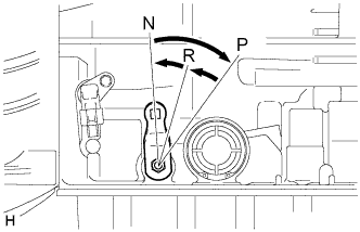 |
Turn the control shaft lever clockwise until it stops, and then turn it counterclockwise 2 notches to set it to the N position.
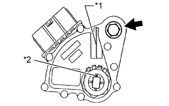 |
Align the neutral basic line with the switch groove, and tighten the bolt.
| *1 | Neutral Basic Line |
| *2 | Groove |
Using a screwdriver, bend the tabs of the lock washer.
Connect the switch connector.
| 2. INSPECT SHIFT LEVER POSITION |
When moving the shift lever from P to R with the ignition switch ON and the brake pedal depressed, make sure that the shift lever moves smoothly and correctly into position.
Start the engine and make sure that the vehicle moves forward after moving the shift lever from N to D, and moves rearward after shifting to the R.
If the results are not as specified, inspect the park/neutral position switch and check the shift lever.
| 3. ADJUST SHIFT LEVER POSITION |
|
Loosen the park/neutral position switch bolt and move the shift lever to N.
Align the switch groove with the neutral basic line.
Hold the switch in position and tighten the bolt.
| *1 | Neutral Basic Line |
| *2 | Groove |
After adjustment, perform the inspection (Click here).
| 4. INSPECT PARK/NEUTRAL POSITION SWITCH ASSEMBLY |
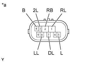 |
Measure the resistance according to the value(s) in the table below.
| Tester Connection | Condition | Specified Condition |
| 4 (B) - 5 (L) | Shift lever in P | Below 1 Ω |
| 2 (RB) - 1 (RL) | Shift lever in R | Below 1 Ω |
| 4 (B) - 5 (L) | Shift lever in N | Below 1 Ω |
| 2 (RB) - 7 (DL) | Shift lever in D or 3 | Below 1 Ω |
| 2 (RB) - 3 (2L) | Shift lever in 2 | Below 1 Ω |
| 2 (RB) - 8 (LL) | Shift lever in L | Below 1 Ω |
| 4 (B) - 5 (L) | Shift lever not in P | 10 kΩ or higher |
| 2 (RB) - 1 (RL) | Shift lever not in R | 10 kΩ or higher |
| 4 (B) - 5 (L) | Shift lever not in N | 10 kΩ or higher |
| 2 (RB) - 7 (DL) | Shift lever not in D or 3 | 10 kΩ or higher |
| 2 (RB) - 3 (2L) | Shift lever not in 2 | 10 kΩ or higher |
| 2 (RB) - 8 (LL) | Shift lever not in L | 10 kΩ or higher |
| *a | Component without harness connected (Park/Neutral Position Switch) |